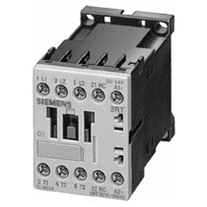
What It Is & Where It Goes
The contactor has four main poles and one instantaneous auxiliary contact (NO/NC configurable by the user). The auxiliary contact is rated at 10 A at 24 V, 2 A at 60 V, 1 A at 110 V, and 0.3 A at 220 V — these are the switching limits for the control circuit, not the main power path.
The AC-4 rating at 400 V is 8.5 A, which is the plugging / inching duty cycle rating; if your application involves frequent reversing or jogging, this is the number that governs contact life, not the AC-2 figure. For resistive loads (AC-12), the maximum operating current is 10 A. The motor power ratings at higher voltages are 4.5 kW at 500 V and 5.5 kW at 690 V — useful if you're feeding a motor on a 690 V industrial network. Short-circuit coordination is defined for Type 2 (no damage to the contactor) with a 20 A gL/gG fuse, and for Type 1 (contactor may need replacement) with a 35 A gL/gG fuse. These are the maximum fuse ratings for the main circuit; the actual fuse size should be coordinated with the upstream protective device. The coil is 24 VDC with a pick-up voltage range of 0.85 to 1.1 times the rated value (20.4 V to 26.4 V). Holding power is 3.3 W — low enough to keep heat rise in a densely packed panel manageable. The coil's closing and holding power are identical, meaning it's a DC-operated contactor with no economizer circuit.
Integration & Wiring
Main circuit terminals are screw-type, accepting 2x (0.5 to 1.5 mm²), 2x (0.75 to 2.5 mm²), or max 2x (0.75 to 4 mm²) solid/stranded, or 2x (20 to 16), 2x (18 to 14), 1x 12 AWG. Auxiliary contact terminals accept the same wire sizes. Mechanical service life is 30 million operating cycles — this is the mechanical endurance, not the electrical life under load. Electrical life will be lower and depends on the switching current and duty cycle.