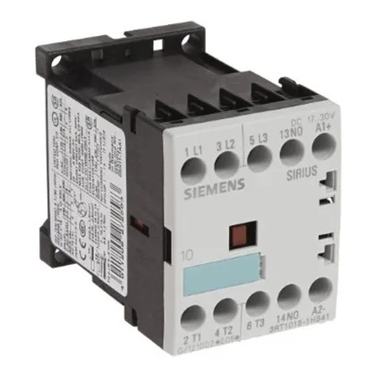
The 3RT1016-1HB41-ZX95: S00 frame contactor, 45 mm wide, 57.5 mm tall, 72 mm deep — fits a standard 35 mm DIN rail per EN 50022, with screw and snap-on mounting. Side-by-side mounting is permitted with 6 mm spacing to adjacent devices for thermal derating. Main circuit screw terminals accept 2x (0.5 to 1.5 mm²) solid, 2x (0.75 to 2.5 mm²) stranded, or up to 2x (0.75 to 4 mm²) max — covers common panel wire sizes. AWG equivalents: 2x (20 to 16), 2x (18 to 14), or single 12 AWG. Strip length and torque follow the terminal marking; the screw cage holds ferruled stranded without issues.
Duty ratings and motor switching
For AC-4 (plugging / inching), rated 8.5 A at 400 V. At 690 V it handles 5.5 kW, useful in 690 V industrial grids or mining applications. The 24 VDC coil draws 2.3 W closing and holding — no economizer needed, the DC coil holds at full power continuously. Auxiliary contact load ratings: 10 A at 24 V, 6 A at 230 V, 3 A at 400 V, 0.3 A at 220 V DC.
Short-circuit coordination
Type 1 coordination: 35 A gL/gG fuse. Type 2 coordination: 20 A gL/gG fuse. The difference matters for downstream selectivity — Type 2 limits let-through energy so the contactor survives a fault without replacement; Type 1 may damage the contactor. For most motor starter applications, spec the 20 A fuse to avoid replacing the contactor after a short.