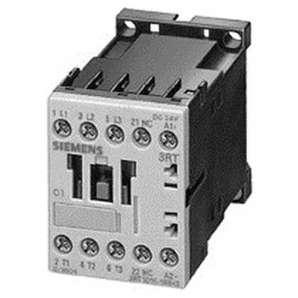
It mounts via screw or snap-on onto 35 mm DIN rail per DIN EN 50022, fitting the standard panel footprint at 45 mm wide, 60 mm tall, and 73 mm deep. The coil is rated 24 V DC with a pick-up and holding power of 3.3 W, and operates reliably between 0.85 and 1.1 times the rated control supply voltage. Main circuit connections use spring-loaded terminals accepting 2x (0.25 to 2.5 mm²) solid or stranded wire, or 2x (24 to 14 AWG).
Motor switching ratings and duty cycles
In AC-3 duty (starting and stopping squirrel-cage motors under load), the contactor is rated for 4.5 kW at 500 V and 5.5 kW at 690 V. At 400 V AC-3, the current rating is not directly listed, but the AC-4 rating at 400 V is 8.5 A, and the AC-2 rating at 400 V is 4 kW. For resistive loads (AC-12), the maximum operating current is 10 A. Auxiliary contact ratings cover DC switching: 10 A at 24 V, 2 A at 60 V, 1 A at 110 V, and 0.3 A at 220 V. The single instantaneous auxiliary contact (1 NO or 1 NC, not specified) provides feedback for PLC or safety circuit integration. The mechanical life is typical 30 million operating cycles.
For fuse coordination, type 1 requires a gL/gG 35 A fuse; type 2 requires a gL/gG 20 A fuse.
Spring-loaded terminals accept 2x (0.25 to 2.5 mm²) conductors; strip length is not specified but standard practice for spring-cage terminals is 8-10 mm.