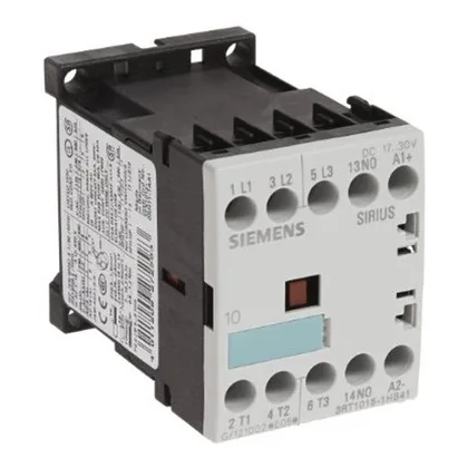
The main circuit uses spring-loaded terminals accepting 2x (0.25 to 2.5 mm²) solid or stranded wire, or 2x (24 to 14 AWG). This saves wiring time compared to screw terminals and resists loosening under vibration. The 24 VDC coil includes a built-in diode surge suppressor, so you don't need an external flyback diode across the coil — one less component to source and mount. Coil holding power is a constant 2.3 W DC, which simplifies PLC output sizing.
The auxiliary contact block carries 10 A at 24 V, 6 A at 230 V, and 3 A at 400 V (AC-12). These are the ratings for control-circuit switching — interlocking, PLC inputs, or indicator lamps. At 24 VDC the same contact switches 10 A, but at 220 VDC it derates to 0.3 A; inductive DC loads need careful checking against the curve. Pollution degree 3 means the contactor is rated for industrial atmospheres with conductive dust or occasional condensation — typical for an unsealed panel in a factory environment. The IP20 rating on the front and terminals means finger-safe but not washdown-rated; keep it inside a cabinet. The 30 million mechanical cycles figure is the expected life without electrical load — useful for estimating maintenance intervals on lightly loaded signal switching.
Dimensions are 45 mm wide, 60 mm tall, and 73 mm deep — the S00 footprint. For type 2 coordination (contactor remains usable after a fault), the fuse drops to 20 A. This is the spec your panel designer needs for the SCCR calculation.