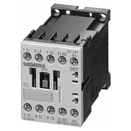
The main current circuit terminates with spring-loaded terminals, accepting 2x (0.25 to 2.5 mm²) solid or stranded conductors, or 2x (24 to 14 AWG). This eliminates routine screw-torque checks during panel build.
For plugging or inching duty (AC-4), the rating is 8.5 A at 400 V. For resistive loads (AC-12), the maximum operating current is 10 A. Motor power ratings are also given: 4.5 kW at 500 V and 5.5 kW at 690 V, covering standard 3-phase induction motors in those voltage classes. The auxiliary contact block carries ratings across multiple voltages: 10 A at 24 V, 6 A at 230 V, 3 A at 400 V, 2 A at 60 V, 1 A at 110 V, and 0.3 A at 220 V. These are the make/break capacities for control-circuit switching — useful when verifying the contact can handle the PLC output or relay load. A built-in varistor surge suppressor is fitted across the coil, so no external suppression module is needed for the DC coil circuit.
Side-by-side mounting is permitted with zero spacing, which keeps the panel width at 45 mm per contactor. The required clearance at the side is 6 mm for heat dissipation when not mounted side-by-side. Dimensions are 45 mm wide, 60 mm tall, and 73 mm deep — compact enough for dense DIN-rail layouts.
For short-circuit coordination, the required fuse for Type 2 coordination is gL/gG 20 A; for Type 1 coordination, gL/gG 35 A. These are the upstream protection values the contactor is tested with.