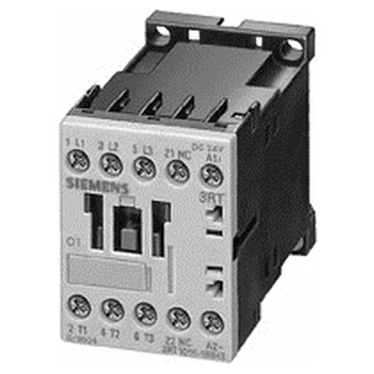
The 24 VDC coil pulls in reliably across a 0.85 to 1.1 times rated voltage at 50 Hz and 0.8 to 1.1 at 60 Hz. At 24 V the main contacts are rated 10 A; for motor duty at 500 V it handles 5.5 kW, and at 690 V also 5.5 kW. Front protection is IP20, so it's safe for finger contact inside an enclosed panel.
The 10 A rating at 24 V is the maximum thermal current (AC-12) for the main contacts — that's the resistive load limit. For motor starting (AC-3), the practical limit is the 5.5 kW figure at 500 V or 690 V. Short-circuit coordination is specified: type 2 coordination requires a gL/gG fuse rated 20 A; type 1 coordination allows a 35 A fuse. That means with a 20 A fuse upstream, the contactor remains usable after a fault (type 2). Pick your fuse based on whether downtime for contactor swap is acceptable. Mechanical endurance is 30 million switching cycles — that's the contactor body life before wear-out, not the electrical life under load. Electrical life depends on the switched current and category; for a 5.5 kW motor started once per minute, expect several hundred thousand operations before contact inspection.
Integration notes
Terminals are screw-type for the main circuit, accepting 2x (0.5 to 1.5 mm²), 2x (0.75 to 2.5 mm²), or max 2x (0.75 to 4 mm²) solid or stranded wire. AWG equivalents are 2x (20 to 16), 2x (18 to 14), or 1x 12. Strip length is standard for the terminal design — no special tooling needed beyond a screwdriver. The contactor has 2 instantaneous auxiliary contacts (form C or form A depends on the specific variant — check the full order code suffix for the auxiliary configuration). These are rated for switching at various voltages: 10 A at 24 V, 2 A at 60 V, 1 A at 110 V, 0.3 A at 220 V, 6 A at 230 V, 3 A at 400 V.