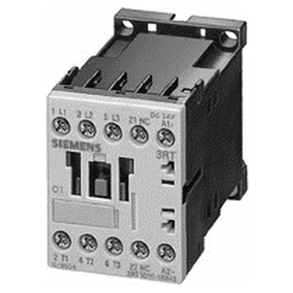
It carries three normally-open (NO) main contacts rated for 10 A at 24 V resistive (AC-12) and delivers 5.5 kW at 400 V in AC-2 duty — the category for slip-ring motor starting and switching. For reversing or plugging duty (AC-4), it handles 8.5 A at 400 V, so it can manage frequent inching or jogging cycles without derating the main contacts. At 45 mm wide and 57.5 mm tall, it fits the S00 footprint, leaving room for auxiliary contact blocks on the side.
The AC-2 rating at 5.5 kW / 400 V is the number that governs motor switching for wound-rotor or slip-ring motors — common in crane and hoist applications where starting current stays under 2.5x full load. For standard squirrel-cage motors, the AC-3 rating (not listed here) would be the usual selection, so verify your motor starting method if you are replacing a general-purpose contactor. The AC-4 rating of 8.5 A at 400 V matters for reversing or jogging duty. If your application cycles the contactor under load more than a few times per hour, this is the current limit — not the AC-2 figure. Exceeding it accelerates contact wear and risks welding. The IP20 front protection keeps fingers and tools out, but the contactor needs to be inside a cabinet for washdown environments. The altitude limit of 2000 m is standard for low-voltage switchgear — above that, dielectric strength and air clearance derate, so factor that in for high-altitude installations.
Main circuit terminals are screw-type, accepting 2x (0.5 to 1.5 mm²) or 2x (0.75 to 2.5 mm²) solid/stranded, with a maximum of 2x (0.75 to 4 mm²). AWG equivalents are 2x (20 to 16) and 2x (18 to 14), with a single 12 AWG also accepted. Strip length and torque are standard for S00 screw terminals — no special tooling needed. These fuse ratings define the maximum short-circuit protection the contactor can withstand — match them to your panel's SCCR calculation. The 6 mm clearance to adjacent devices on the side is the minimum for heat dissipation.