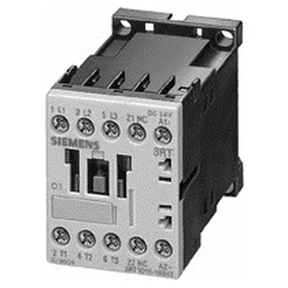
SIRIUS S00 power contactor — 3 NO, screw terminals, 24 VDC coil
It is rated for 5.5 kW at 690 V AC and 5.5 kW at 500 V AC, making it suitable for switching three-phase motor loads in control panels. The contactor uses screw-type terminals for the main current circuit, accepting solid or stranded conductors from 0.5 mm² up to 4 mm² (AWG 20–14). Front and terminal protection is IP20, suitable for enclosed panel environments. The coil voltage tolerance at 60 Hz is 0.8 to 1.1 times rated voltage.
Switching ratings across voltage classes
The 3RT1017-1AV62 carries rated operational currents at multiple voltage levels for resistive and motor loads. At 24 V it switches 10 A, at 60 V it switches 2 A, at 110 V it switches 1 A, at 220 V it switches 0.3 A, at 230 V it switches 6 A, and at 400 V it switches 3 A. For AC-2 duty (slip-ring motors) at 400 V it delivers 5.5 kW, and for AC-4 duty (plugging/inching) at 400 V it delivers 8.5 A. The AC-12 maximum operating current is 10 A. The 60 Hz rated voltage is 480 V. The contactor has zero instantaneous contacts and zero NC main contacts — all three main poles are normally open.
Dimensions are 45 mm wide, 57.5 mm high, and 72 mm deep — the S00 footprint fits standard 45 mm DIN-rail spacing. Side clearance of 6 mm is required for airflow when mounted side-by-side. The screw terminals accept 2x (0.5–1.5 mm²), 2x (0.75–2.5 mm²), or max 2x (0.75–4 mm²) solid or stranded conductors. AWG equivalents are 2x (20–16), 2x (18–14), or 1x 12.