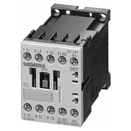
The coil draws 3.3 W on closing and 3.3 W holding — a fixed-gap magnetic circuit that stays at full power once pulled in, so no economizer circuit is needed. The pickup threshold is 0.85 x rated voltage (about 20.4 VDC), and dropout is 1.1 x rated voltage (about 26.4 VDC) — meaning the contactor pulls in reliably at a sag and drops out cleanly when the control supply rises above nominal. That 1.1 dropout is unusual: most contactors drop out below nominal. This one stays held until the voltage exceeds 26.4 V, so a floating DC supply that drifts high won't cause chatter.
The motor ratings define the real-world load envelope. At AC-3 duty (squirrel-cage motors, starting and disconnecting under load) it delivers 5.5 kW at 400 V and 5.5 kW at 500 V and 690 V — so it handles a standard 7.5 hp motor at 400 V three-phase, and the same power at higher voltages because the current drops. At AC-4 (plugging, inching) it is rated 8.5 A at 400 V, which is about 4 kW — roughly half the AC-3 power, reflecting the higher thermal stress of reversing duty. The auxiliary contact ratings cover DC switching: 10 A at 24 V, 2 A at 60 V, 1 A at 110 V, 0.3 A at 220 V, and 6 A at 230 V AC. These DC ratings are the ones that matter for PLC interposing or pilot-duty circuits — the 10 A at 24 V is generous for a size S00 auxiliary contact. Short-circuit coordination is specified: with type 2 coordination (limited damage, contactor remains usable) use a 20 A gL/gG fuse; with type 1 coordination (contactor may need replacement) use a 35 A gL/gG fuse.
Side-by-side mounting is permitted, so multiple contactors can be ganged without spacing. The 45 mm width (3 TE on a DIN rail) and 57.5 mm height fit standard panel layouts. Depth is 72 mm, which leaves clearance for wiring ducts or busbars behind the rail. Wire range: solid or stranded, 2x (0.5 to 1.5 mm²) and 2x (0.75 to 2.5 mm²) per terminal, max 2x (0.75 to 4 mm²). AWG equivalents are 2x (20 to 16) and 2x (18 to 14), with a single 12 AWG allowed.
The substance prohibition date of 2006-07-01 aligns with RoHS compliance — the part is RoHS-compliant as manufactured.