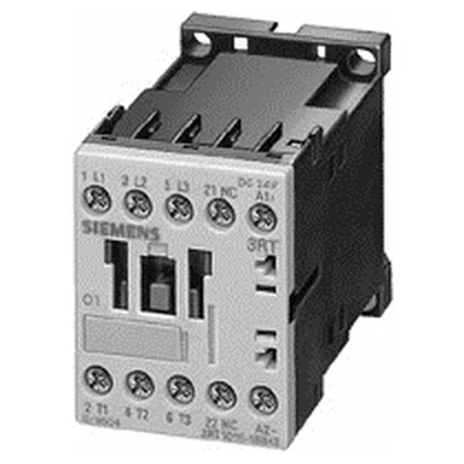
This contactor is rated for motor switching at 5.5 kW in AC-3 duty at 400 V and also at 690 V, making it suitable for standard 400 V three-phase induction motors up to that power.
If your application involves frequent reversing or jogging, the AC-4 figure governs contact life, not the AC-3 number. Short-circuit coordination is specified: for Type 2 coordination, use a gL/gG fuse rated 20 A; for Type 1, a 35 A fuse is required. This means the contactor will withstand a fault up to the prospective short-circuit current without welding its contacts (Type 2) or with acceptable contact damage (Type 1), provided the listed fuse is upstream. The magnet coil draws 3.3 W DC both for closing and holding — a single-wattage coil, not a two-stage economized design. This is a constant DC load on the control supply, so factor it into your 24 VDC power budget if you are ganging several contactors. Auxiliary contact ratings are given across the voltage range: 10 A at 24 V, 6 A at 230 V, 3 A at 400 V, and 0.3 A at 220 V DC. These are the switching capacities for the built-in auxiliary contacts — use the DC rating for pilot duty on PLC inputs or relay coils. This is the mechanical endurance without electrical load — actual electrical life will be lower and depends on the switched current and duty category.
Mounting and integration details
Side-by-side mounting is permitted with zero side clearance — the 6 mm spacing to adjacent devices is a minimum for heat dissipation, not a mandatory gap. The S00 frame is 45 mm wide, 57.5 mm tall, and 72 mm deep, so it fits standard 80 mm deep enclosures. Main circuit terminals are screw-type, accepting 2x (0.5 to 1.5 mm²), 2x (0.75 to 2.5 mm²), or max 2x (0.75 to 4 mm²) solid or stranded wire. AWG equivalents are 2x (20 to 16), 2x (18 to 14), and 1x 12. The dual-wire entry is useful for daisy-chaining power through the contactor without a separate terminal block.
Compliance documentation is standard for Siemens industrial controls: the part carries CE marking for the European market and is designed to meet IEC/EN 60947-4-1 for contactors and motor-starters. UL and CSA listings are typical for this series, though the specific approvals for this order code should be confirmed on the nameplate or via the manufacturer's declaration of conformity.