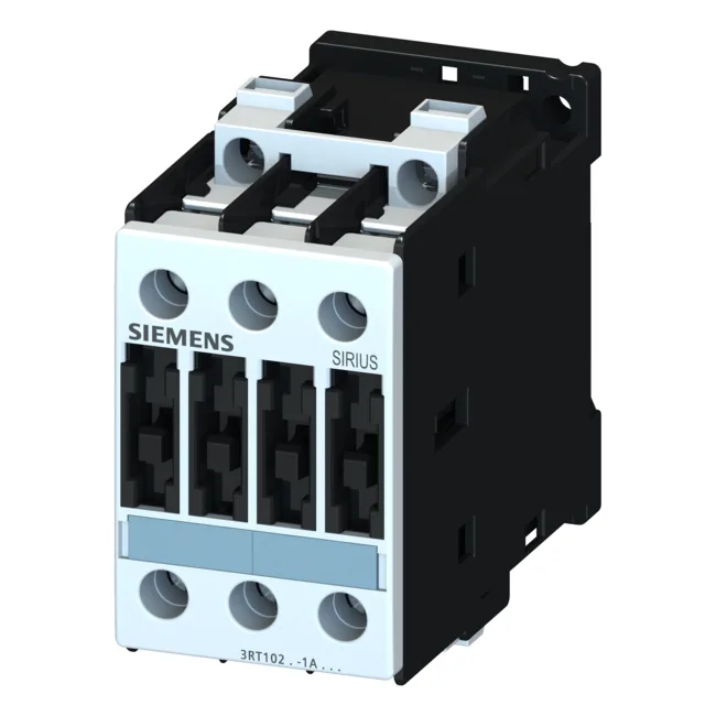
It carries 3 normally-open main contacts and zero normally-closed main contacts, so it is a straight three-pole make device — no auxiliary break on the main poles.
For less demanding AC-2 duty (starting and running slip-ring motors), it is rated 4 kW at 400 V. The AC-12 maximum operating current of 10 A covers resistive loads like heaters. For motor switching at higher voltages, the contactor is rated 4.5 kW at 500 V and 5.5 kW at 690 V. That makes it suitable for 400 V class motors in the 4 kW range, and for 690 V applications where the motor draw fits the current limit. DC switching capacity is specified: 10 A at 24 V, 2 A at 60 V, 1 A at 110 V, 0.3 A at 220 V. These are resistive DC ratings — inductive DC loads will need derating or arc suppression. Short-circuit coordination is defined: Type 1 coordination requires a 63 A gL/gG fuse; Type 2 coordination (where the contactor must remain operational after a fault) requires a 25 A gL/gG fuse. This is critical for panel builders sizing protection. The terminal body itself is IP00, so live parts are exposed behind the panel door.
Main circuit terminals are screw-type, accepting solid conductors: 2x 0.5–1.5 mm², 2x 0.75–2.5 mm², max 2x 0.75–4 mm². Stranded conductors: 2x 1–2.5 mm², 2x 2.5–6 mm², max 2x 10 mm². AWG equivalents: 2x 16–12, 2x 14–10, 1x 8. The 2x (two-wire) capacity is useful for looping through to a second device. Side-by-side mounting is permitted with 6 mm spacing on the side, which saves panel width when ganging multiple contactors.
Same part, different passport: the 3RT1023-1AF04 is the standard European-spec order code. If you see a 3RT1023-1AL20 in your panel BOM, that is a coil-voltage variant — the 1AF04 has a 110 V 50 Hz coil. The mechanical frame and contact ratings are identical, so the swap is a coil-voltage decision, not a fit decision. Let me be transparent: if your panel was wired for 110 V coil, the 1AF04 drops straight in without rewiring the power circuit.