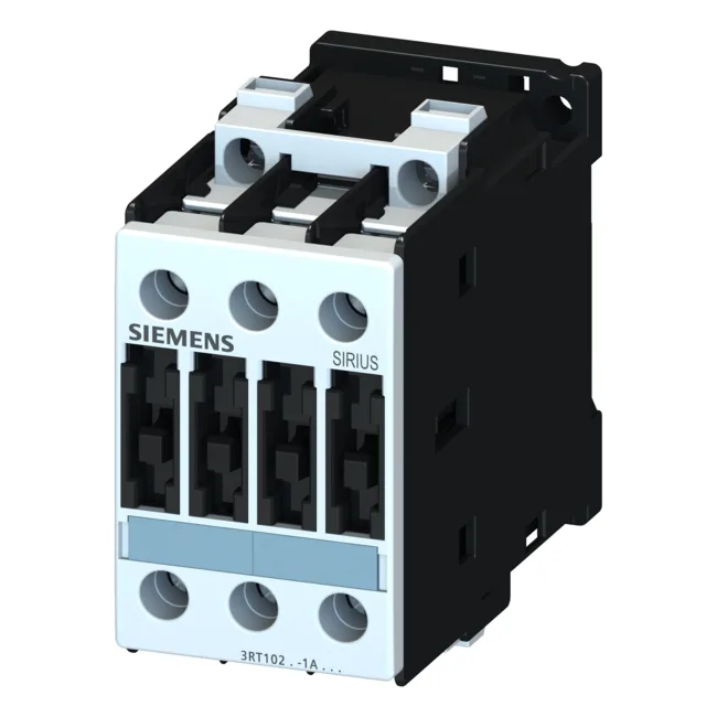
Rated for AC-2 duty at 4 kW and AC-4 at 8.5 A, both at 400 V, this contactor handles reversing, plugging, and inching applications where the motor is switched under load.
Motor power ratings: 4.5 kW at 500 V and 5.5 kW at 690 V. These are the maximum three-phase induction motor loads the contactor can switch in AC-3 duty. If your motor nameplate falls within these, the 3RT1023-1AN60 is sized correctly for continuous switching. The auxiliary contact block carries 10 A at 24 V, 6 A at 230 V, and 0.3 A at 220 V DC. The DC ratings drop sharply with voltage — at 220 V DC the 0.3 A limit is the one to watch for inductive loads like relay coils or small DC solenoids. This means it's suited for typical industrial environments but not for clean rooms or sealed enclosures without condensation management. Maximum operating altitude of 2 000 m. Above that, dielectric strength and cooling derate — if your installation is at elevation, factor that in.
Accepts solid conductors: 2x (0.5 to 1.5 mm²), 2x (0.75 to 2.5 mm²), max 2x (0.75 to 4 mm²). For stranded: 2x (1 to 2.5 mm²), 2x (2.5 to 6 mm²), max 2x 10 mm². AWG equivalents: 2x (16 to 12), 2x (14 to 10), 1x 8. This covers most panel wiring from signal-level to moderate power feeds. Type 2 requires 25 A. The Type 2 coordination limits fault energy to prevent contact welding, so if your panel design specifies Type 2, use the 25 A fuse.
That's the mechanical life of the contactor assembly — electrical life will be lower depending on the switching load and duty cycle.
Dimensions: 85 mm height, 45 mm width, 91 mm depth. Side-by-side mounting is permitted (zero spacing between units), which saves rail space in dense panels. Front protection is IP20 (finger-safe), while the terminal area is IP00 (open terminals) — so the panel enclosure provides the overall ingress protection. Rated control supply voltage: 200 V at 50 Hz, 200 to 220 V at 60 Hz. The coil operates across 0.8 to 1.1 times the rated voltage at 50 Hz, and 0.85 to 1.1 at 60 Hz. This means the coil holds in reliably even if the control supply sags 20% at 50 Hz or 15% at 60 Hz.