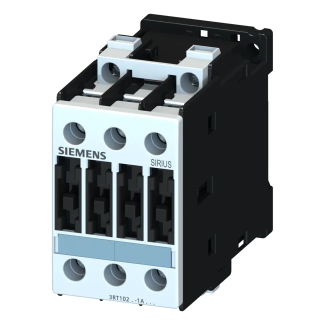
Contactor selection brief
The AC-12 resistive load maximum is 10 A, suitable for heater or lighting banks. Short-circuit coordination is specified for both Type 1 and Type 2. With Type 1 (welding permitted but no fire risk), the fuse can be gL/gG 63 A. This lets the panel designer choose between tighter protection and higher fault tolerance.
Terminal and wiring data
Main circuit terminals are screw-type, accepting 2x (1 to 2.5 mm²), 2x (2.5 to 6 mm²), or a single conductor up to 10 mm². The AWG equivalents are 2x (16 to 12), 2x (14 to 10), or 1x 8 AWG. Auxiliary contact terminals accept 2x (0.5 to 1.5 mm²), 2x (0.75 to 2.5 mm²), or a maximum of 2x (0.75 to 4 mm²). Strip lengths and torque values follow the standard Siemens SIRIUS terminal schedule. This is typical for industrial control panels not in sealed or climate-controlled environments. The front face carries IP20 finger protection; the terminals themselves are IP00, so they must be guarded within the enclosure.
Coil and auxiliary contact ratings
The coil operates at 230 V 50 Hz with a voltage tolerance of 0.8 to 1.1 times the rated value, so the pickup range is 184 V to 253 V. Dropout typically occurs below about 0.6 times rated, per the SIRIUS family characteristic. The coil draws a holding current consistent with the S0 frame size; inrush is higher during pickup but the control transformer should be sized for the sealed VA. Auxiliary contacts (integrated or add-on block) are rated for switching at various voltages: 10 A at 24 V, 6 A at 230 V, 3 A at 400 V, and 0.3 A at 220 V DC. These ratings follow the IEC 60947-5-1 utilization categories. For DC switching at higher voltages, the current must be derated significantly due to arc extinction limits.