What it is and what it does
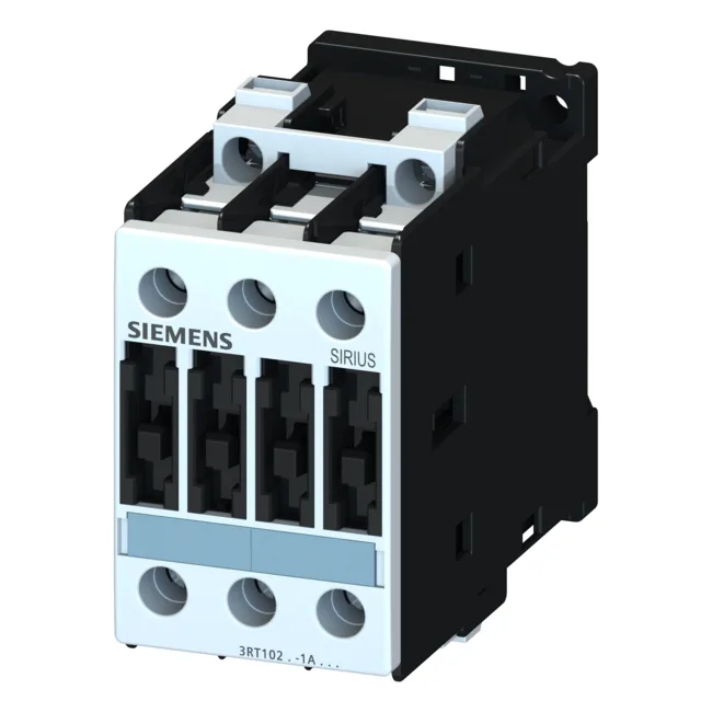
The Siemens 3RT1023-1BD40 is a SIRIUS power contactor in the S0 frame size, designed for switching motor loads and resistive circuits in control panels. It mounts via screw and snap-on onto 35 mm standard mounting rail per DIN EN 50022, which means it drops into a standard panel layout without adapter plates. The screw-type terminals on the main current circuit accept solid conductors from 0.5 mm² up to 4 mm² (2x per clamp), matching typical panel wiring practice for this frame class. The coil is rated at 24 VDC with a holding power of 5.4 W — that's the steady-state draw the PLC output or relay must sink. Closing and holding power are identical at 5.4 W, so there's no inrush spike to trip a marginal 24 VDC supply. The contactor carries a maximum operating current of 10 A under AC-12 duty (resistive loads), and at 24 V rated value it switches 10 A in DC circuits. For motor duty, it's rated at 4 kW at AC-2 at 400 V, and 8.5 A at AC-4 at 400 V for reversing or inching applications.
What the ratings mean for fit
The S0 frame is a compact 45 mm wide, 85 mm tall, and 101 mm deep — that's the envelope to check against existing DIN rail clearance. Side-by-side mounting is permitted with 6 mm spacing at the side, so you can gang multiple contactors on a rail without forced derating, as long as the ambient stays within -25 to +60 °C during operation. The front face carries IP20 protection (finger-safe), but the terminal area is only IP00 — that means the wiring zone is exposed; keep it behind a panel door or cover. For coordination, the part requires a gL/gG fuse of 25 A for Type 2 coordination (no damage to the contactor under short circuit), and 63 A for Type 1 coordination (contactor may need replacement after fault). That's a practical difference: if the upstream protection is sized for Type 1, the contactor is sacrificial in a fault event. The pollution degree is rated 3 (conductive pollution or dry non-conductive pollution that becomes conductive due to condensation), which is standard for industrial control panels not in clean-room environments.
Integration notes
The reference code per DIN EN 81346-2 is Q, which designates it as a switching device in the functional structure of a panel schematic. The contactor carries a mechanical endurance of 10 million typical operations — that's the rated life before the mechanism wears, not the electrical life under load. Electrical life depends on the switched current and duty cycle; for resistive loads at rated current it will be lower than the mechanical figure. The maximum operating altitude is 2 000 m without derating; above that, air density affects arc extinction and thermal dissipation. Terminal wiring: the main circuit accepts solid conductors 2x (0.5 to 1.5 mm²), 2x (0.75 to 2.5 mm²), max 2x (0.75 to 4 mm²). For stranded conductors, it accepts 2x (1 to 2.5 mm²), 2x (2.5 to 6 mm²), max 2x 10 mm². AWG equivalents are 2x (16 to 12), 2x (14 to 10), 1x 8. Strip length and torque spec aren't in this record, but the terminal type is screw-type, so use a torque screwdriver per Siemens installation instructions.
