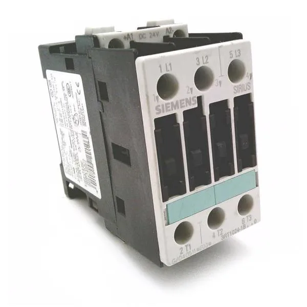
It carries a 24 VDC coil and is rated for AC-4 duty at 12.5 A at 400 V — that's the plugging/reversing/inching current, the toughest switching category for a contactor because it makes and breaks locked-rotor current.
If your application is simple on/off across-the-line starting (AC-3), the contactor will handle a higher current, but the evidence doesn't list that figure directly. Short-circuit coordination matters here. With Type 2 coordination (minimal damage to the contactor after a fault), the required upstream fuse is 25 A gL/gG. That's the fuse the panel builder needs to spec — not the motor overload relay. The auxiliary contact block has 2 instantaneous contacts, rated at 10 A at 24 V, 6 A at 230 V, and 3 A at 400 V. That's enough for PLC inputs or relay coils in most control circuits. Above that, you'd need to account for reduced air density affecting dielectric withstand and cooling.
That's the S0 frame envelope — it fits the standard DIN rail footprint. The depth of 140 mm means you need at least that much clearance behind the panel door for the contactor body and wiring. Main circuit terminals accept screw-type connections: 2x (1 to 2.5 mm²) or 2x (2.5 to 6 mm²) stranded, max 2x 10 mm². For solid wire: 2x (0.5 to 1.5 mm²) or 2x (0.75 to 2.5 mm²), max 2x (0.75 to 4 mm²). AWG equivalents: 2x (16 to 12) or 2x (14 to 10), max 1x 8 AWG. That covers most motor leads up to about 4 kW at 400 V. Front face is IP20 — finger-safe when installed in an enclosure. The terminal area itself is IP00, so the contactor needs to be inside a panel with a door or cover. Electrical life will be shorter and depends on the switching current and duty cycle.
The 3RT1024-1AL24-3MA0 is the 24 VDC coil variant of the S0 frame contactor. If your BOM calls for a different coil voltage (e.g., 24 VAC, 110 V, 230 V), the frame size and ratings are similar but the coil suffix changes. The evidence doesn't list a direct successor or alternate MPN — this is the current production version.