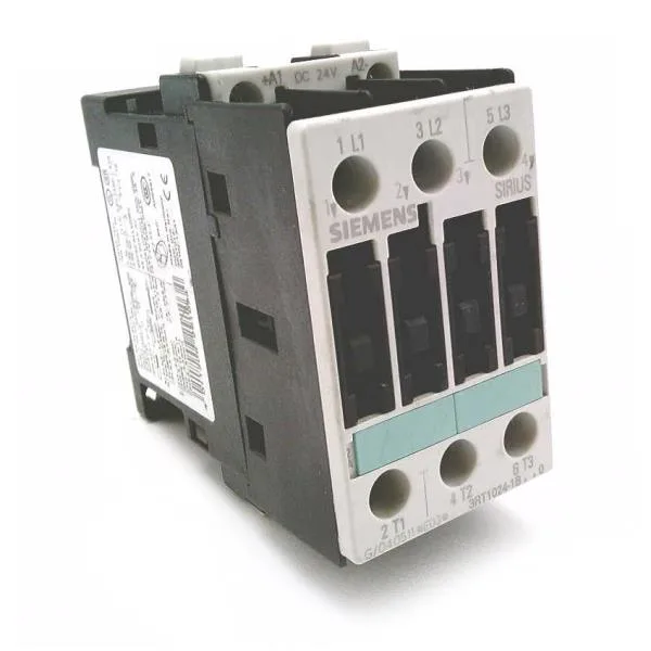
The Siemens SIRIUS 3RT1024-1BM44 is a size S0 power contactor designed for switching motor loads in industrial control panels. It mounts via screw or snap-on onto a standard 35 mm DIN rail per DIN EN 50022, fitting into a 45 mm wide slot that leaves 6 mm clearance to adjacent devices on each side when mounted side-by-side. The front face carries an IP20 rating — finger-safe for panel installation — while the terminal area is rated IP00, meaning the wiring compartment is not touch-safe once the cover is removed. This is typical for contactors; the panel builder accounts for it with enclosure selection.
Rated duty and motor power
In AC-3 duty — the standard category for starting squirrel-cage motors and disconnecting them under running conditions — the 3RT1024-1BM44 delivers 7.5 kW at both 500 V and 690 V. At 400 V AC-2 (slip-ring motor duty) it is rated for 5.5 kW. The AC-4 rating, used for reversing or inching duty where the contactor breaks stalled-rotor current, is 12.5 A at 400 V. For resistive loads (AC-12) the maximum continuous current is 10 A. The auxiliary contact block provides 2 instantaneous contacts; their switching capacity is listed at 10 A at 24 V, 6 A at 230 V, and derated to 0.3 A at 220 V DC.
Coil and control circuit
The magnet coil draws 5.4 W during both closing and holding — a DC-operated coil consuming the same power in both states, simplifying the control transformer sizing. The operating temperature range of -25 to +60 °C covers most indoor panel environments, and pollution degree 3 (conductive pollution or dry non-conductive pollution that becomes conductive due to condensation) means the contactor is suited for industrial atmospheres without additional conformal coating. The maximum operating altitude is 2 000 m, after which dielectric strength derating applies per IEC 60947-1. Short-circuit coordination requires a gL/gG fuse: 25 A for type 2 coordination (no damage to the contactor), 63 A for type 1 (contactor may need replacement after fault).
Termination and wiring
Main circuit terminals are screw-type, accepting 2x (1 to 2.5 mm²), 2x (2.5 to 6 mm²), or a single 10 mm² conductor. The solid/stranded auxiliary terminal range is 2x (0.5 to 1.5 mm²) and 2x (0.75 to 2.5 mm²), max 2x 4 mm². AWG equivalents for the main contacts are 2x (16 to 12), 2x (14 to 10), and 1x 8. The 150 mm depth includes the arc chamber overhang, so panel depth must accommodate it beyond the DIN-rail mounting foot.
