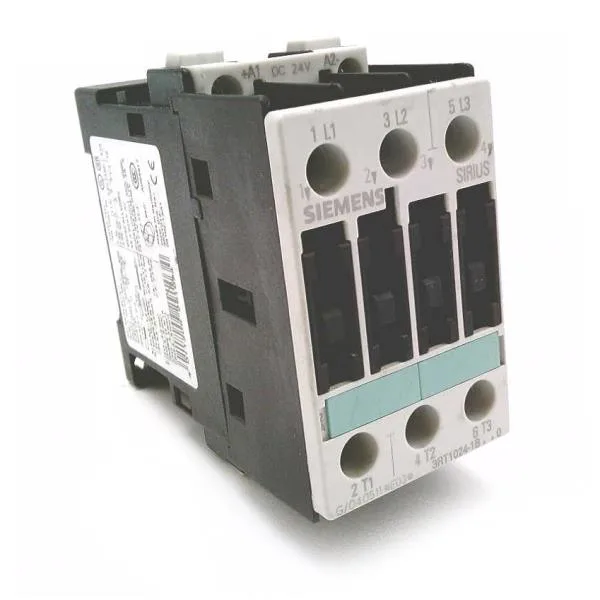
The 24 V DC coil includes an integrated varistor surge suppressor, which suppresses back-EMF during de-energization — a detail that matters when the coil is driven by a PLC output or solid-state relay that cannot absorb inductive kickback. For motor duty, the AC-3 rating at 400 V is 7.5 kW, meaning it switches a 3-phase induction motor up to that load under full running current.
The coil draws 4.2 W both at pickup and hold — a constant-holding-power design that simplifies the control transformer sizing. The 24 V DC coil holds above 18 V typical dropout; the integrated varistor means no external free-wheel diode is needed, but verify polarity: the suppressor is polarity-sensitive. This governs the branch circuit protection design. The main contacts accept screw-type terminals rated for 2x (0.5...1.5 mm²) solid, 2x (0.75...2.5 mm²) stranded, or up to 2x 4 mm² max. For AWG: 2x (16...12) solid, 2x (14...10) stranded, or 1x 8. The 6 mm clearance to adjacent components on the side is the minimum for heat dissipation.
Auxiliary contact ratings and mechanical life
The auxiliary contact block (integrated or add-on) carries rated operational currents: 10 A at 24 V, 6 A at 230 V, 3 A at 400 V, and 0.3 A at 220 V DC. These ratings are for the control circuit; the DC switching capability at 220 V (0.3 A) is notably limited — verify the inductive load current if switching DC contactors or relays. Electrical life depends on the switched current and duty cycle; for AC-3 motor switching at full rating, expect roughly 1–2 million operations before contact replacement.