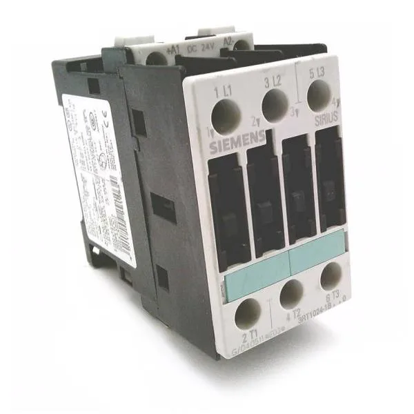
Siemens SIRIUS 3RT1024-1XP00-0GA0 — power contactor, S0 frame, built-in varistor
Motor duty ratings — AC-2 and AC-4 at 400 V
For AC-4 reversing or inching duty, the rating is 12.5 A at 400 V — that's the current the contacts must interrupt during plugging or jogging cycles, where the load current stays high through the break. Type 1 coordination allows a 63 A gL/gG fuse upstream; Type 2 coordination requires a 25 A gL/gG fuse to limit let-through energy and protect the contactor from weld damage during a short circuit.
Coil and auxiliary contact ratings
The built-in varistor suppresses the coil surge at dropout — no external snubber needed for the 24 V DC coil. The auxiliary contact block is rated 10 A at 24 V DC (AC-12), 6 A at 230 V, and derates to 0.3 A at 220 V DC and 0.2 A at 60 V DC. These ratings govern the pilot duty load the auxiliary contacts can switch — a PLC digital output or a relay coil, for instance — and the DC curve drops fast because DC arcs sustain longer than AC.
Wiring and panel fit
The screw terminals accept solid or stranded conductors: 2x (0.5–1.5 mm²) or 2x (0.75–2.5 mm²) for the auxiliary circuit, and 2x (1–2.5 mm²) or 2x (2.5–6 mm²) for the main circuit, with a maximum of 2x 10 mm². AWG equivalents are 2x (16–12) and 2x (14–10) for the main contacts. The contactor footprint is 45 mm wide × 116 mm high × 101 mm deep — the 45 mm width is a standard 2.5-module DIN-rail slot, so it replaces an existing S0 contactor without re-drilling the backplate. Side-by-side mounting is permitted with 6 mm spacing to adjacent devices for heat dissipation.