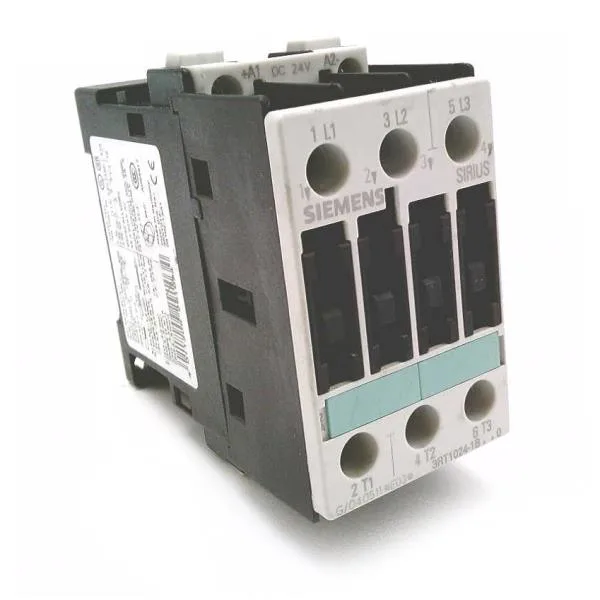
It's a current-production part, so no lifecycle surprises for a BOM line. Rated for AC-2 duty at 5.5 kW and AC-4 at 12.5 A, both at 400 V — that's the motor-switching curve you need for reversing or plugging applications, not just resistive loads. The AC-4 figure governs the inrush and breaking of locked-rotor current, so size your motor protection accordingly. Mounts on 35 mm DIN rail per EN 50022 with a snap-on action — no tools for the rail, but the screw-type terminals on the main circuit (accepting 2x 1–2.5 mm² or 2x 2.5–6 mm², up to 2x 10 mm²) need a screwdriver for the power wiring.
Side-by-side mounting is permitted with no derating gap needed — stack them tight on the rail. Altitude rating to 2,000 m without derating. For Type 1 coordination (no damage but may weld contacts) use a 63 A gL/gG fuse upstream. For Type 2 coordination (contacts remain unweldable after a fault) step down to a 25 A gL/gG fuse. That's a real difference in protection philosophy — Type 2 keeps the contactor reusable after a short-circuit event.
Compared to the smaller 3RT1016-1AG61, this S0-frame 3RT1024 carries higher AC-4 current (12.5 A vs the 1016's lower rating) and a full 5.5 kW AC-2 capability, so it's the right pick when the motor load exceeds what a compact frame can handle. The 3RT1023-1AL20 shares the same S0 frame but offers different auxiliary contact configurations — verify your NC/NO count on the aux stack before swapping.
The product designation as a power contactor aligns with IEC 60947-4-1 scope.
Auxiliary contact ratings: 10 A at 24 V, 6 A at 230 V, 2 A at 60 V, 1 A at 110 V, 0.3 A at 220 V, and 3 A at 400 V — all at 50 Hz. That covers the typical control voltage range for PLC outputs and relay coils in most panels. Wire range for the main screw terminals: solid or stranded 2x 0.25–2.5 mm², 2x 1–2.5 mm², 2x 2.5–6 mm², or a single conductor up to 10 mm². AWG equivalents: 2x 16–12, 2x 14–10, or 1x 8 AWG. That gives flexibility for both European metric and North American wiring practices.