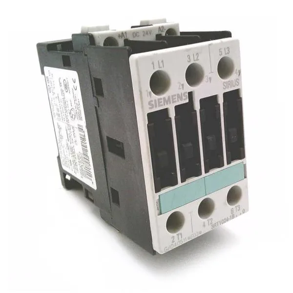
Terminal design and wiring constraints
Main power circuit terminals are screw-type, accepting 2x (0.25... 2.5 mm²) solid or 2x (1... 2.5 mm²) stranded, with a maximum of 2x 10 mm². Auxiliary and control circuit terminals are spring-loaded, which speeds wiring on the control side and holds well under vibration in a panel. For Type 1 coordination (allow contactor replacement after fault), the fuse can be 63 A. That gives the panel designer flexibility on selectivity with downstream motor protection.
Environmental and mounting fit
The contactor is rated IP20 on the front of the enclosure and IP00 at the terminals — meaning the terminal area is not finger-safe, so it needs to live inside a panel with a door or cover. Dimensions are 45 mm wide, 88 mm high, and 140 mm deep.
Auxiliary contact and surge suppression
The contactor includes 2 instantaneous auxiliary contacts. The surge suppressor is built with RC elements, which limits coil voltage spikes on dropout — relevant if the control circuit shares a DC supply with electronics like a PLC output. Auxiliary contact ratings are given for DC switching: 10 A at 24 V, 2 A at 60 V, 1 A at 110 V, and 0.3 A at 220 V. These are the DC-13 (inductive) values, so they govern the contact life when switching small relays or contactor coils directly.