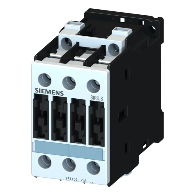
The coil is rated 24 VDC, and the contactor draws 10 A at that voltage (AC-12 duty). For motor switching, the AC-2 rating at 400 V is 7.5 kW, and the AC-4 rating at 400 V is 15.5 A — so it handles reversing or inching duty cycles where the contacts make and break under load. Keep that in mind during panel layout: the terminal zone isn't touch-safe on its own.
The main circuit handles up to 11 kW at 690 V and 10 kW at 500 V — so it's sized for moderate three-phase motor loads in 400 V or 690 V systems. For DC switching, the ratings drop with voltage: 10 A at 24 V, 2 A at 60 V, 1 A at 110 V, 0.3 A at 220 V, and 6 A at 230 V. That's typical for a contactor — the arc extinguishes less efficiently on DC, so the current capacity falls as voltage rises. If you're switching DC loads, size accordingly.
Wiring and integration details
Main circuit terminals are screw-type, accepting solid or stranded conductors: 2x (0.5…1.5 mm²), 2x (0.75…2.5 mm²), and up to 2x (0.75…4 mm²) for the smaller range; for larger wires, 2x (1…2.5 mm²), 2x (2.5…6 mm²), and max 2x 10 mm². AWG equivalents are 2x (16…12), 2x (14…10), and 1x 8. That covers most panel wiring up to about 8 AWG. Side-by-side mounting is allowed, with a 6 mm gap to the side for airflow and arc clearance. No forced spacing needed, but don't crowd it tight. For short-circuit protection, type 1 coordination calls for a 63 A gL/gG fuse; type 2 coordination requires a 25 A gL/gG fuse. That's the difference between a fuse that blows and protects the contactor (type 2) versus one that allows limited damage to the contactor (type 1). Match the fuse to your coordination requirement.