What It Is and Where It Fits
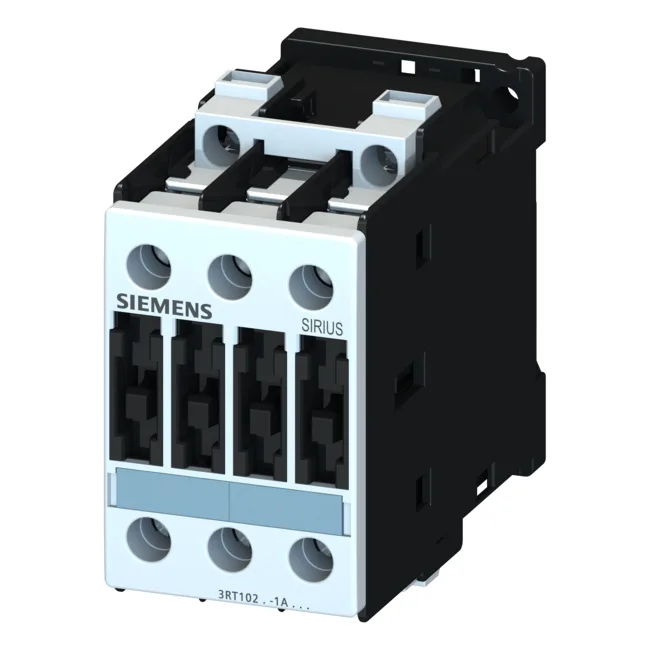
The 3RT1025-1AP00-ZW96: This is a Siemens SIRIUS power contactor in the S0 frame size, with three normally-open main contacts and screw-type terminals for the main circuit. It mounts on a 35 mm DIN rail per DIN EN 50022, using either screws or the integrated snap-on clip — standard panel integration for a control cabinet. The front face carries IP20 protection (finger-safe), while the terminal area is IP00, meaning the wiring zone expects enclosure-level protection.
Key Ratings and What They Mean for Your Load
Rated for 7.5 kW at AC-2 duty (400 V), this contactor handles slip-ring motor loads — starting and stopping under moderate inrush. For AC-4 duty (plugging, inching, reversing), it carries 15.5 A at 400 V, which is the rating that governs frequent switching of squirrel-cage motors. The coil is 230 V at 50 Hz, with an operating range of 0.8 to 1.1 times rated voltage — so it pulls in reliably down to about 184 V and holds through line dips. Mechanical endurance is 10 million cycles; the contactor is rated for pollution degree 3 (industrial environment with conductive or dry non-conductive pollution) and operates from -25 °C to +60 °C. Maximum altitude is 2 000 m without derating. Auxiliary contact ratings cover control voltages: 10 A at 24 V, 2 A at 60 V, 1 A at 110 V, 0.3 A at 220 V, 6 A at 230 V, and 3 A at 400 V — these are the switching limits for pilot devices, PLC inputs, or relay coils in the control circuit.
Integration and Wiring Notes
Screw terminals accept solid conductors: 2x (0.5 to 1.5 mm²), 2x (0.75 to 2.5 mm²), max 2x (0.75 to 4 mm²). For stranded, the range is 2x (1 to 2.5 mm²), 2x (2.5 to 6 mm²), max 2x 10 mm². AWG equivalents for main contacts: 2x (16 to 12), 2x (14 to 10), 1x 8. Side-by-side mounting is allowed with 6 mm clearance to adjacent devices. Type 2 coordination (no damage to the contactor under short circuit) requires a gL/gG fuse rated 25 A; Type 1 coordination (contactor may need replacement after fault) uses a 63 A gL/gG fuse. The reference code per DIN EN 81346-2 is Q.
