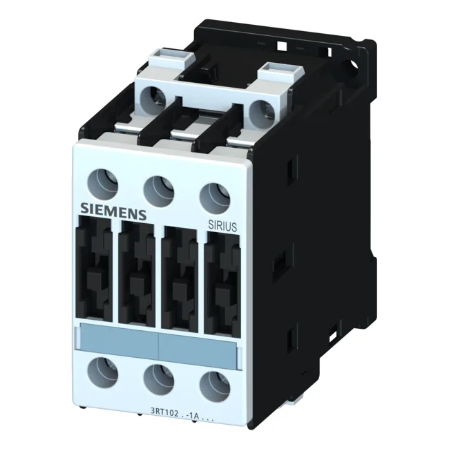
Rated for motor duty at 11 kW at 690 V AC-3 and 10 kW at 500 V AC-3, it handles the typical pump, fan, and conveyor loads found in a 400 V to 690 V distribution system. The contactor mounts via screw or snap-on onto a 35 mm DIN rail per DIN EN 50022, and its 45 mm width and 91 mm depth fit the standard S0 panel footprint. Front-side protection is IP20, meaning tools and fingers are kept out during operation.
Main circuit terminals are screw-type, accepting solid conductors from 2x 0.5 mm² up to max. 2x 4 mm², and stranded from 2x 1 mm² up to max. 2x 10 mm². The terminal layout is sized for the S0 frame — expect to land motor leads and line-side feeders within that cross-section range. Side-by-side mounting is permitted with no additional gap, which saves DIN-rail space when ganging multiple contactors for a star-delta or reversing starter.
For a BOM freeze or second-source review, the closest functional peer is the 3RT1017-1AP01, which shares the same S0 frame size and screw-terminal format. The key difference is that the 3RT1017-1AP01 is a lower-rated variant — it tops out at 5.5 kW at 400 V AC-3 versus the 3RT1025-1AV00's 7.5 kW at 400 V AC-3. Verify your motor full-load amps before substituting downward.
For Type 2 coordination (contactor remains fully functional after a fault), the fuse drops to gL/gG 25 A. The contactor is rated for switching at 50 Hz, with the coil operating range at 0.8 to 1.1 times the rated voltage at that frequency. For 60 Hz systems, verify coil compatibility separately — the listed ratings are at 50 Hz.