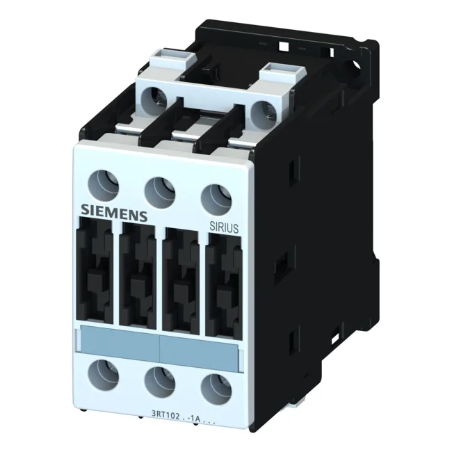
Siemens 3RT1025-1BB40-ZW96 — Contactors

Siemens 3RT1025-1BB40-ZW96 SIRIUS Power Contactor, 24 VDC, S

MPN3RT1025-1BB40-ZW96

Siemens SIRIUS, power contactor, 3RT1025-1BB40-ZW96, S0 frame, 24 VDC coil, screw terminals, 45 mm width, IP20 front, current production.

Source DocumentedChannel stated on listing & quote
Condition PhotosReal unit photos / video on request
WhatsApp AnswersFast human replies for machine-down parts
Worldwide DispatchDHL/FedEx — transit quoted per order
Independent China distributor & sourcing agent· Listing updated Sep 2026

Specifications

3RT1025-1BB40-ZW96 — Identification
ParameterValue
Contactor frame sizeS0
3RT1025-1BB40-ZW96 — Ratings & Performance
ParameterValue
Rated operational current, AC-12, max.10 A
Rated operational current, AC-4 @ 400 V15.5 A
Rated value @ 400 V3 A
Rated value @ 500 V10 kW
Rated value @ 690 V11 kW
Rated value @ 230 V6 A
Rated value @ 24 V10 A
Rated value @ 60 V2 A
Rated value @ 110 V1 A
Rated value @ 220 V0.3 A
3RT1025-1BB40-ZW96 — Control & Coil
ParameterValue
Control supply voltage typeDC
3RT1025-1BB40-ZW96 — Contacts & Poles
ParameterValue
Main poles3
Main NO contacts3
Auxiliary contact reliability1 faulty switching per 100 million (17 V, 1 mA)
3RT1025-1BB40-ZW96 — Protection & Coordination
ParameterValue
Short-circuit coordination type 1, fusefuse gL/gG: 63 A
Short-circuit coordination type 2, fusefuse gL/gG: 25 A
Aux. switch short-circuit protection, fusefuse gL/gG: 10 A
3RT1025-1BB40-ZW96 — Connection & Mounting
ParameterValue
Main circuit connectionscrew-type terminals
Aux. / control circuit connectionscrew-type terminals
Conductor cross-section, solid2x (0.5 ... 1.5 mm²), 2x (0.75 ... 2.5 mm²), max. 2x (0.75 ... 4 mm²)
Conductor cross-section, solid or stranded2x (1 ... 2,5 mm²), 2x (2,5 ... 6 mm²), max. 2x 10 mm²
Conductor cross-section, finely stranded w/ ferrule2x (0.5 ... 1.5 mm²), 2x (0.75 ... 2.5 mm²)
Mounting methodscrew and snap-on mounting onto 35 mm standard mounting rail according to DIN EN 50022
Side-by-side mountingYes
3RT1025-1BB40-ZW96 — Durability
ParameterValue
Durability (operating cycles, typ.)10 000 000
Durability with aux. switch block (cycles, typ.)10 000 000
3RT1025-1BB40-ZW96 — Environmental
ParameterValue
Operating temperature range-25 ... +60 °C
Installation altitude, max.2 000 m
3RT1025-1BB40-ZW96 — Mechanical
ParameterValue
Width45 mm
Height85 mm
Depth101 mm

Product details

The 24 VDC coil draws 5.4 W during both closing and holding, so the control transformer can be sized for continuous draw rather than a surge peak. Screw-type terminals on both the main and auxiliary circuits — no special crimp tooling needed for the panel build.

Motor switching ratings and coordination

For AC-4 duty (plugging, inching, reversing) the limit is 15.5 A at 400 V, which is the figure to use when the application cycles the motor against a locked rotor. At 500 V the contactor handles 10 kW; at 690 V it handles 11 kW. Type 1 coordination requires a 63 A gL/gG fuse upstream; Type 2 coordination needs a 25 A gL/gG fuse.

The 45 mm width and 85 mm height fit standard S0 footprint; depth is 101 mm including coil terminals. Side-by-side mounting is permitted, so multiple contactors pack tightly on the rail without derating.

Frequently asked questions

What is the depth of 3RT1025-1BB40-ZW96?

The depth is 101 mm, measured from the mounting surface to the front of the coil terminals.

Will 3RT1025-1BB40-ZW96 drop into a panel built for 3RT1015-1BB42?

Both are S0 frame contactors with the same 45 mm width and DIN-rail mounting, so the mechanical footprint is identical. The main difference is the coil voltage — 3RT1025-1BB40-ZW96 uses 24 VDC, while 3RT1015-1BB42 uses a different coil. Verify the control circuit voltage before swapping.

MPN
3RT1025-1BB40-ZW96