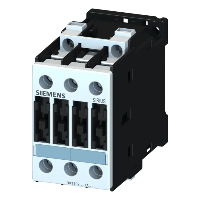
Its S0 frame size (45 mm width, 85 mm height, 150 mm depth) leaves room for adjacent devices on the rail.
Electrical Ratings and Duty
Rated coil voltage is 24 VDC, with a closing and holding power of 5.4 W. The coil operates between 0.8 × and 1.1 × the rated value, so it pulls in reliably down to about 19.2 V and holds through supply dips up to 26.4 V. For main circuit switching, the AC-12 operational current is 10 A maximum. Motor-duty ratings include 7.5 kW at AC-2 / 400 V and 15.5 A at AC-4 / 400 V. At 690 V, it handles 11 kW, making it suitable for 400 V and 690 V motor circuits. Auxiliary and control circuits use screw-type terminals accepting 2×(0.5…1.5 mm²) solid or 2×(0.75…2.5 mm²) stranded, with a maximum of 2×(0.75…4 mm²). Main circuit terminals accept up to 2×(2.5…6 mm²) stranded or 1×10 mm².
Protection and Coordination
The contactor carries IP20 on the front (finger-safe) and IP00 at the terminals, so it requires enclosure protection for the wiring zone. For type 2 coordination, a gL/gG fuse rated 25 A is required; for type 1 coordination, a 63 A gL/gG fuse.