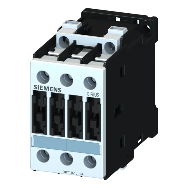
The 45 mm width and 85 mm height keep the footprint compact for dense enclosures. Rated for AC-2 duty at 7.5 kW on 400 V and 11 kW on 690 V, this contactor handles slip-ring motor starting and reversing loads. For resistive loads, the AC-12 rating at 10 A defines the maximum continuous current for non-inductive circuits like heater banks. DC switching capability is specified across four voltage levels: 10 A at 24 V, 2 A at 60 V, 1 A at 110 V, and 0.3 A at 220 V. These are the make/break capacities for DC loads where arc extinction is harder than AC — relevant for brake coils, DC valve solenoids, or battery-backed control circuits.
The 11 kW at 690 V extends the same duty to higher-voltage three-phase systems common in heavy industrial plants. The AC-4 current of 15.5 A at 400 V sets the limit for reversing or jogging applications — expect shorter electrical life if you cycle near this rating frequently. This simplifies the control transformer sizing: budget 5.4 W steady-state per contactor. These values determine the upstream fuse selection in your distribution board and affect the SCCR rating of the entire panel assembly.
Mounting and Wiring Integration
The main circuit uses screw-type terminals accepting 2x (0.5...1.5 mm²), 2x (0.75...2.5 mm²), max 2x (0.75...4 mm²) for solid conductors, or 2x (1...2.5 mm²), 2x (2.5...6 mm²), max 2x 10 mm² for stranded. AWG equivalents are 2x (16...12), 2x (14...10), 1x 8. This range covers most motor feeder cables up to 4 mm² solid or 6 mm² stranded without needing terminal adapters. Front protection is IP20 — safe against finger contact when mounted in a panel. The terminal area itself is IP00, meaning the connection points are not touch-safe until the panel door is closed. The maximum operating altitude is 2000 m without derating; above that, dielectric strength and air clearance must be reviewed per IEC 60947-1.
For a buyer filling a BOM line, the key fit confirmations are: Size S0 footprint (45 mm wide), AC-2 motor power at your system voltage, and the 24 V DC coil (the -1BD40 suffix indicates the coil voltage). The mechanical life of 10 million operations means this contactor will outlast most machinery overhauls in normal cycling service.