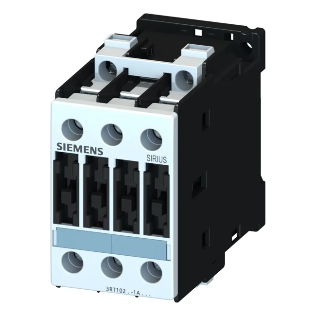
Compared to the smaller-frame 3RT1023-1AL20, the 3RT1025-1BD44-1AA0 carries higher motor ratings across the voltage range — 11 kW at 690 V versus the 1023's lower kW ceiling — and adds a second NC auxiliary contact. Both share the S0 footprint and 45 mm width, so a swap into an existing panel is mechanically straight; check the coil voltage (24 VDC here) and the main-circuit lug capacity (up to 4 mm² solid or 10 mm² stranded per terminal) before committing the BOM.
Wire range: main contacts accept 2x (0.5…1.5 mm²) solid, 2x (0.75…2.5 mm²) stranded, or up to 2x 4 mm²; auxiliary contacts use 2x (1…2.5 mm²) solid or 2x 10 mm² stranded max.
Coil pick-up and hold power are both 5.4 W DC — no inrush spike to design around. The magnet coil is rated for continuous duty at 24 VDC; closing and holding power are identical, so the coil driver sees a constant load. Short-circuit coordination: Type 1 requires a 63 A gL/gG fuse; Type 2 requires a 25 A gL/gG fuse.