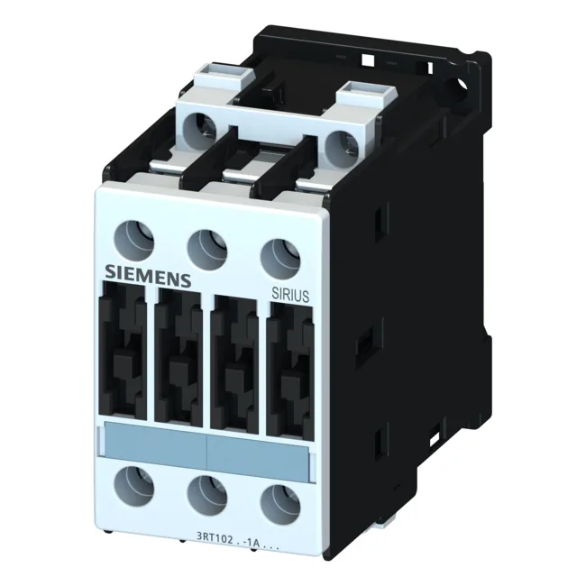
It mounts via screw or snap-on onto 35 mm DIN rail per EN 50022, with a compact footprint of 45 mm width, 85 mm height, and 101 mm depth — fitting standard panel layouts without oversizing the enclosure. Rated at 10 A for AC-12 resistive loads and 7.5 kW at 400 V for AC-2 duty (slip-ring motors), it also handles 15.5 A at 400 V in AC-4 duty for reversing or inching applications. For AC-3 direct-on-line motor starting, it delivers 10 kW at 500 V and 11 kW at 690 V — the rating that governs the real motor sizing decision.
Termination, coordination, and auxiliary switching
Main circuit terminals accept screw-type connections: solid conductors 2x (0.5–1.5 mm²), 2x (0.75–2.5 mm²), max 2x (0.75–4 mm²); stranded 2x (1–2.5 mm²), 2x (2.5–6 mm²), max 2x 10 mm². AWG equivalents for main contacts are 2x (16–12), 2x (14–10), 1x 8. This covers most panel wiring from signal-level to motor branch circuits without adapters. Type 1 coordination allows up to 63 A gL/gG. The auxiliary contact block switches 10 A at 24 V DC, 2 A at 60 V DC, 1 A at 110 V DC, and 0.3 A at 220 V DC — enough for PLC inputs or relay coils in the control circuit.
Environmental limits and protection
Front-side protection is IP20 (finger-safe); the terminal area is IP00 — ensure the enclosure provides the final protection barrier.