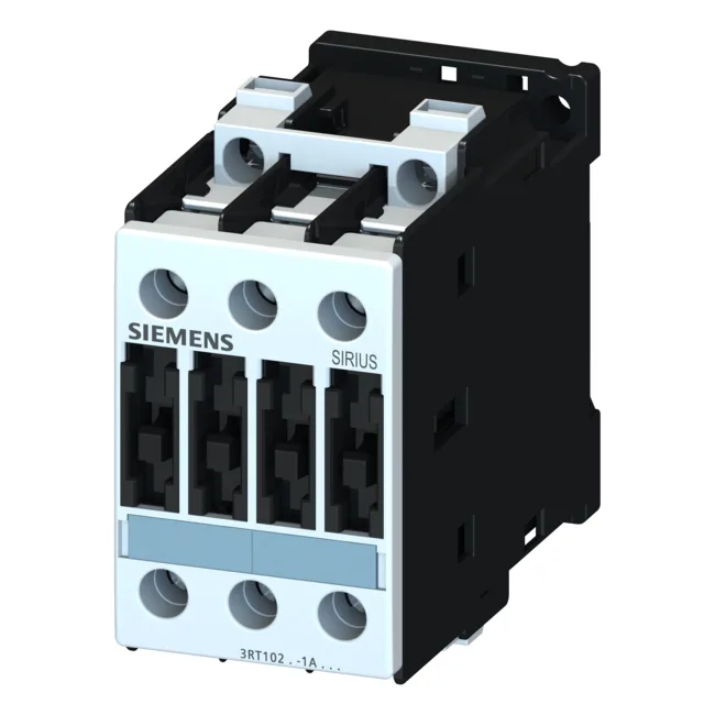
Siemens 3RT1025-3BW40 — Contactors

Siemens 3RT1025-3BW40 SIRIUS Power Contactor, S0 Frame, 10 k

MPN3RT1025-3BW40

Siemens SIRIUS power contactor, size S0, 3RT1025-3BW40, screw-type terminals, DC operated coil, 10 kW at 500 V AC-3.

Source DocumentedChannel stated on listing & quote
Condition PhotosReal unit photos / video on request
WhatsApp AnswersFast human replies for machine-down parts
Worldwide DispatchDHL/FedEx — transit quoted per order
Independent China distributor & sourcing agent· Listing updated Sep 2026

Specifications

3RT1025-3BW40 — Identification
ParameterValue
Contactor frame sizeS0
3RT1025-3BW40 — Ratings & Performance
ParameterValue
Rated operational current, AC-4 @ 400 V15.5 A
Rated value @ 400 V3 A
Rated value @ 500 V10 kW
Rated value @ 690 V11 kW
Rated value @ 230 V6 A
Rated value @ 24 V10 A
Rated value @ 60 V2 A
Rated value @ 110 V1 A
Rated value @ 220 V0.3 A
3RT1025-3BW40 — Control & Coil
ParameterValue
Control supply voltage typeDC
3RT1025-3BW40 — Contacts & Poles
ParameterValue
Main poles3
Main NO contacts3
Auxiliary contact reliability1 faulty switching per 100 million (17 V, 1 mA)
3RT1025-3BW40 — Protection & Coordination
ParameterValue
Short-circuit coordination type 1, fusefuse gL/gG: 63 A
Short-circuit coordination type 2, fusefuse gL/gG: 25 A
Aux. switch short-circuit protection, fusefuse gL/gG: 10 A
3RT1025-3BW40 — Connection & Mounting
ParameterValue
Main circuit connectionscrew-type terminals
Conductor cross-section, solid2x (0.25 ... 2.5 mm²)
Conductor cross-section, finely stranded w/ ferrule2x (0.25 ... 1.5 mm²)
Side-by-side mountingYes
3RT1025-3BW40 — Durability
ParameterValue
Durability (operating cycles, typ.)10 000 000
Durability with aux. switch block (cycles, typ.)10 000 000
3RT1025-3BW40 — Environmental
ParameterValue
Operating temperature range-25 ... +60 °C
3RT1025-3BW40 — Mechanical
ParameterValue
Width45 mm
Height85 mm
Depth100 mm

Product details

Rated for AC-3 duty at 10 kW on a 500 V supply and 11 kW at 690 V, this contactor handles the motor starting and running currents typical of pumps, fans, and compressors up to that power band. The DC magnet coil draws 5.4 W to close and holds at the same 5.4 W, which means the coil driver sees a steady load without a power drop-off after pickup — a detail that matters when sizing the 24 VDC supply for a panel with multiple contactors.

The IP20 front enclosure protects against finger contact; the terminals themselves are IP00, meaning the wiring compartment is open to the panel environment. Main circuit screw terminals accept solid or stranded wire: 2x (0.25 to 2.5 mm²) or 2x (2.5 to 6 mm²), with a maximum of 2x 10 mm². For AWG, that translates to 2x (16 to 12) or 2x (14 to 10), with a single 8 AWG as the max. The auxiliary contact block (not included with this base unit) uses 2x (0.25 to 2.5 mm²) solid.

For Type 2 coordination (contactor remains operational after a fault), use a gL/gG 25 A fuse. These values govern the upstream short-circuit protective device selection — a decision the panel builder must make before wiring.

Frequently asked questions

What are the key motor power ratings for this contactor?

It is rated for 10 kW at 500 V AC-3 and 11 kW at 690 V AC-3. For AC-4 duty (reversing/inching) at 400 V, the rated operational current is 15.5 A.

What wire sizes does the main circuit accept?

Screw terminals accept 2x (0.25 to 2.5 mm²), 2x (2.5 to 6 mm²), or max 2x 10 mm². In AWG: 2x (16 to 12), 2x (14 to 10), or 1x 8.

Can this contactor be mounted side-by-side with others?

Yes, side-by-side mounting is permitted, allowing dense packing on the DIN rail without required spacing between units.

MPN
3RT1025-3BW40