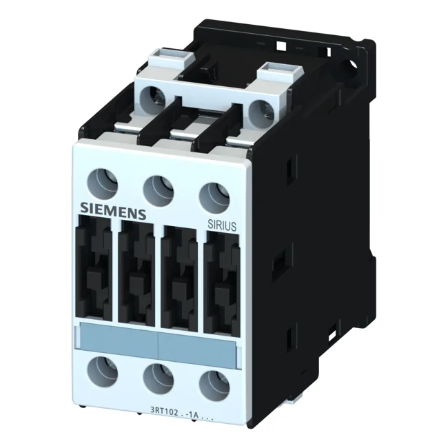
The S0 frame means it fits a 45 mm wide footprint — tight enough for a multi-row cabinet, but you'll want to mind the 140 mm depth when laying out gland plates or door-mount components.
Main current circuit terminals are screw-type, accepting solid conductors: 2x (0.5 to 1.5 mm²), 2x (0.75 to 2.5 mm²), and max 2x (0.75 to 4 mm²). For stranded, it handles 2x (1 to 2.5 mm²), 2x (2.5 to 6 mm²), and max 2x 10 mm². That's enough for the 35 A gL/gG fuse required for Type 2 coordination, or the 100 A fuse for Type 1 coordination. If you're pulling 10 AWG, the terminal accepts 1x 8 AWG — one wire per clamp.
Coordination and fault handling
With Type 2 coordination (no welding of contacts under fault), the required upstream fuse is 35 A gL/gG. For Type 1 coordination (welding allowed but no fire risk), it's 100 A gL/gG. That's a wide selectivity window — you can size the branch protection to the load without over-fusing the contactor.