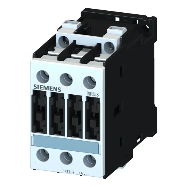
This contactor carries 11 kW ratings at both 500 V and 690 V under AC-2 duty, and an AC-4 current rating of 15.5 A at 400 V. The AC-2 rating covers wound-rotor motors and slip-ring applications; the AC-4 rating handles inching, plugging, and reversing — the high-stress cycles that generate arcing across the main contacts. Three instantaneous main contacts (3 NO) handle the power circuit, and the contactor is built for 10 million typical mechanical cycles. That mechanical life is what you expect from a S0-frame SIRIUS unit — it's not a light-duty relay, it's meant for daily switching in a production line.
The 11 kW AC-2 rating at 500 V and 690 V tells you this contactor is sized for medium-horsepower induction motors — think 15 HP at 460 V or 20 HP at 575 V, roughly. Front protection is IP20 (finger-safe), terminal area is IP00 (open). That's standard for panel-mount contactors — the IP20 front means an operator can touch the front of the installed unit without risk, but the wiring area needs to be inside a locked enclosure.
Main circuit terminals are screw-type, accepting 2x (1 to 2.5 mm²) solid/stranded, 2x (2.5 to 6 mm²), or max 2x 10 mm² — also AWG equivalents 2x (16 to 12), 2x (14 to 10), 1x 8. Auxiliary contacts accept 2x (0.5 to 1.5 mm²), 2x (0.75 to 2.5 mm²), max 2x (0.75 to 4 mm²). That's generous for a Size S0; you can parallel two 4 mm² conductors per terminal for high-current feeds. For Type 2 coordination (no-weld after fault), the manufacturer specifies a gL/gG fuse of 35 A. For Type 1 coordination (welding allowed, but no fire risk), the fuse goes up to 100 A gL/gG. If you're designing to IEC 60947-4-1, the 35 A fuse limit is the one that protects downstream equipment after a short circuit. Physical dimensions: 55 mm wide, 85 mm high, 140 mm deep. The 55 mm width is the key panel-space number — it occupies three 18 mm module positions on a DIN rail, which is standard for S0 contactors.
The auxiliary contact ratings span 10 A at 24 V, 6 A at 230 V, down to 0.3 A at 220 V DC. These are the values for the integrated auxiliary contacts — they cover typical PLC-level control signals and pilot duty circuits. The DC ratings are the limiting factor: at 220 V DC the contacts only handle 0.3 A, so verify your DC load before wiring. Above that, expect reduced dielectric strength and lower switching capacity — standard for industrial contactors per IEC 60947.