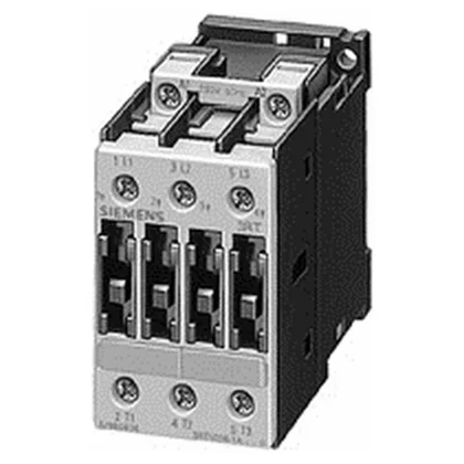
SIRIUS 3RT1026-1AV60 — what it is and what drives the fit
The 3RT1026-1AV60 is a Siemens SIRIUS power contactor in the size S0 frame, 45 mm wide, with three normally-open main poles and screw-type terminals for the main current circuit. It is rated for AC-4 duty at 15.5 A at 400 V — the switching category that governs reversing, inching, and plugging applications where the contactor makes and breaks motor starting current, not just running current. That AC-4 figure, not the AC-1 resistive rating, is the one that decides fit for a motor load that sees frequent starts or reversals. For AC-2 (slip-ring motor starting) or AC-3 (squirrel-cage motor starting and switching off under load), the contactor carries 11 kW at 400 V. Mounting is screw-and-snap-on to a 35 mm DIN rail per DIN EN 50022, with side-by-side mounting permitted — no derating gap required between units on the rail. The front face carries IP20 protection; the terminals themselves are IP00, so the panel builder should account for clearance around the wiring zone. Operating temperature range is -25 to +60 °C, and the unit is rated for pollution degree 3, meaning it tolerates conductive dust and humidity typical of industrial control panels.
Coordination and wire sizing — what the ratings mean for panel integration
Type 1 coordination (no damage to the enclosure, contactor may be unusable after a short) requires a gL/gG fuse rated 100 A upstream. Type 2 coordination (contactor remains operational after a short) calls for a 35 A gL/gG fuse. These are the maximum fuse ratings for the respective coordination types — the actual selection depends on the downstream motor full-load current and the upstream breaker. Wire sizing for the main circuit accepts solid or stranded conductors: 2x (1 to 2.5 mm²) or 2x (2.5 to 6 mm²), with a maximum of 2x 10 mm². AWG equivalents are 2x (16 to 12), 2x (14 to 10), or 1x 8 AWG. Auxiliary contact wiring takes 2x (0.5 to 1.5 mm²) or 2x (0.75 to 2.5 mm²), max 2x (0.75 to 4 mm²). Mechanical endurance is rated at 10 million operating cycles — that is the mechanical life of the contactor assembly, not the electrical life under load. Electrical life will be lower and depends on the switching category, current, and frequency of operation. The contactor carries no built-in suppression for the coil; the installer provides the appropriate RC snubber or free-wheel diode across the coil terminals per the load type.
