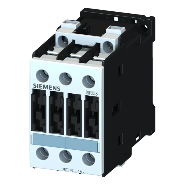
The Siemens 3RT1026-1BB40-ZW97 is a SIRIUS S0-frame power contactor with a 24 VDC magnet coil, rated for motor switching at 11 kW on 400 V AC-3 duty and also 11 kW at 500 V and 690 V. It uses screw-type terminals for the main circuit and mounts via screw or snap-on onto a 35 mm DIN rail per EN 50022 — the S0 frame keeps the footprint compact at 45 mm wide, 85 mm tall, and 101 mm deep.
The 24 VDC coil draws 5.4 W on both closing and holding — a steady-state load that matters for DC supply sizing in a panel with multiple contactors. The AC-3 motor rating of 11 kW at 400 V is the number that governs most three-phase motor switching; the same contactor also carries 11 kW at 500 V and 690 V, so it handles higher-voltage motors without derating the power. For resistive or general-purpose loads, the AC-12 rating tops out at 10 A. Switching capacity on the DC side covers control-circuit loads: 10 A at 24 V, 2 A at 60 V, 1 A at 110 V, and 0.3 A at 220 V. The AC-4 rating at 400 V is 15.5 A — that's the inching or plugging duty cycle, lower than AC-3 because of the heavier arc stress during frequent reversals. The operating temperature range of -25 to +60 °C covers most indoor industrial panels, though the coil's minimum pickup voltage (0.8 × rated) and dropout (0.1 × rated) should be checked against the actual DC supply regulation.
Side-by-side mounting is allowed with a 6 mm gap to the side — no derating mentioned for adjacent units, but the gap ensures airflow. The main circuit screw terminals accept 2x (1 to 2.5 mm²) solid or stranded, up to 2x 10 mm² maximum. The auxiliary/coil terminals take 2x (0.5 to 1.5 mm²) solid, up to 2x 4 mm². AWG equivalents are 2x (16 to 12) for the main and 2x (16 to 14) for the coil circuit.
These values guide the selection of branch-circuit protection in the panel.