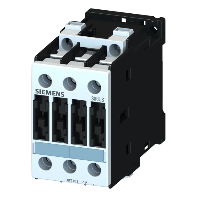
The 24 VDC coil draws 5.4 W on closing and holds at the same 5.4 W. Pickup voltage threshold is 0.8 x rated, dropout below 1.1 x rated. On the main poles, AC-3 switching at 400 V delivers 11 kW, enough for a 15 kW motor at 400 V three-phase. Resistive (AC-12) load handling tops out at 10 A.
The 24 VDC auxiliary contact ratings are graded by voltage: 10 A at 24 V, 2 A at 60 V, 1 A at 110 V, 0.3 A at 220 V, 6 A at 230 V, 3 A at 400 V, and 11 kW at both 500 V and 690 V. That last pair means the contactor can switch a motor load at 690 V three-phase, not just the common 400 V — useful in mining or marine installations where 690 V distribution is standard. Short-circuit coordination: with type 2 coordination (no welding after fault), the required upstream fuse is 35 A gL/gG. For type 1 (welding allowed), a 100 A gL/gG fuse is permitted. This lets the panel designer choose between tighter selectivity and simpler fuse sizing. The S0 frame is 45 mm wide, 85 mm tall, 101 mm deep — a compact footprint that fits two contactors per standard 100 mm DIN-rail segment.
Screw-type terminals on the main circuit accept 2x (1 to 2.5 mm²), 2x (2.5 to 6 mm²), or max 2x 10 mm² stranded — or 2x (16 to 12 AWG), 2x (14 to 10 AWG), or 1x 8 AWG solid. The auxiliary contact terminals accept 2x (0.5 to 1.5 mm²), 2x (0.75 to 2.5 mm²), or max 2x (0.75 to 4 mm²). That range covers most panel wiring from signal-level to motor feeders. IP20 on the front (finger-safe) and IP00 at the terminals means the contactor body is protected against accidental contact, but the terminal area is open — standard for panel-mount contactors where the enclosure provides the overall IP rating.
The -ZX95 suffix indicates a customer-specific variant. The base 3RT1026-1BB40 (without suffix) shares the same ratings and form factor.