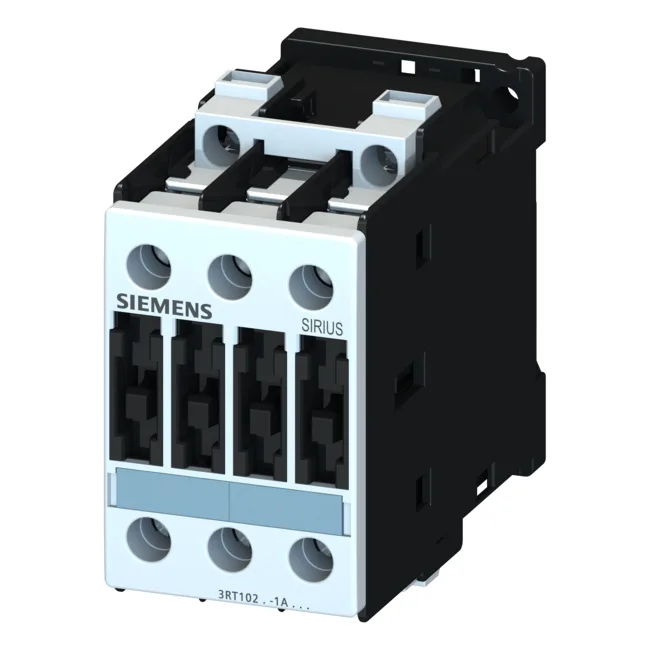
The S0 frame is 45 mm wide, 119 mm tall, 100 mm deep — plan for that depth behind the gland plate; it's not a shallow panel part. IP20 on the front face, IP00 at the terminals — so the terminals need to be inside the enclosure, not poking through a cutout. Main circuit connections are screw-type terminals accepting 2x (0.25 to 2.5 mm²) solid, 2x (1 to 2.5 mm²) or 2x (2.5 to 6 mm²) stranded, max 2x 10 mm². AWG equivalents: 2x (16 to 12), 2x (14 to 10), 1x 8.
For Type 2 coordination (contactor remains fully operational after a fault), the fuse drops to gL/gG 35 A. That's a big difference in let-through energy — if your panel spec calls for Type 2, make sure the fuse is 35 A, not 100 A. Maximum altitude 2,000 m without derating. Rated frequency 50 Hz.