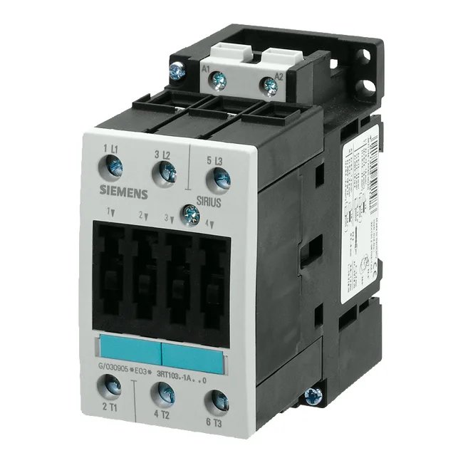
Siemens 3RT1033-3AK60 — Contactors

Siemens 3RT1033-3AK60 SIRIUS Power Contactor, S2 Size, 11 kW

MPN3RT1033-3AK60

Siemens SIRIUS 3RT1033-3AK60 power contactor, size S2, 3-pole, screw terminals, 11 kW at 500 V, 9.5 kW at 690 V, 50/60 Hz.

Source DocumentedChannel stated on listing & quote
Condition PhotosReal unit photos / video on request
WhatsApp AnswersFast human replies for machine-down parts
Worldwide DispatchDHL/FedEx — transit quoted per order
Independent China distributor & sourcing agent· Listing updated Sep 2026

Specifications

3RT1033-3AK60 — Identification
ParameterValue
Contactor frame sizeS2
3RT1033-3AK60 — Ratings & Performance
ParameterValue
Rated operational current, AC-12, max.10 A
Rated operational current, AC-4 @ 400 V15.5 A
Rated value @ 400 V3 A
Rated value @ 500 V11 kW
Rated value @ 690 V9.5 kW
Rated value @ 230 V6 A
Rated value @ 24 V10 A
Rated value @ 60 V2 A
Rated value @ 110 V1 A
Rated value @ 220 V0.3 A
3RT1033-3AK60 — Control & Coil
ParameterValue
Control supply voltage typeAC
Rated value @ 50 Hz0.8 ... 1.1
Rated value @ 50 Hz110 V
3RT1033-3AK60 — Contacts & Poles
ParameterValue
Main poles3
Main NO contacts3
Auxiliary contact reliability1 faulty switching per 100 million (17 V, 1 mA)
3RT1033-3AK60 — Protection & Coordination
ParameterValue
Short-circuit coordination type 1, fusefuse gL/gG: 125 A
Short-circuit coordination type 2, fusefuse gL/gG: 63 A
Aux. switch short-circuit protection, fusefuse gL/gG: 10 A
3RT1033-3AK60 — Connection & Mounting
ParameterValue
Main circuit connectionscrew-type terminals
Aux. / control circuit connectionspring-loaded terminals
Conductor cross-section, solid2x (0.25 ... 2.5 mm²)
Conductor cross-section, solid or stranded2x (0.75 ... 16 mm²)
Conductor cross-section, finely stranded w/ ferrule2x (0.25 ... 1.5 mm²)
Mounting methodscrew and snap-on mounting onto 35 mm standard mounting rail according to DIN EN 50022
Side-by-side mountingYes
3RT1033-3AK60 — Durability
ParameterValue
Durability (operating cycles, typ.)10 000 000
Durability with aux. switch block (cycles, typ.)10 000 000
3RT1033-3AK60 — Environmental
ParameterValue
Operating temperature range-25 ... +60 °C
Storage temperature range-55 ... +80 °C
Installation altitude, max.2 000 m
3RT1033-3AK60 — Mechanical
ParameterValue
Width55 mm
Height112 mm
Depth115 mm
3RT1033-3AK60 — Specifications
ParameterValue
At AC15g / 5 ms, 8g / 10 ms

Product details

Rated for 11 kW at 500 V and 9.5 kW at 690 V, this contactor handles medium-horsepower motors — think pumps, conveyors, or fans in a 400 V to 690 V distribution. The S2 frame keeps the panel footprint tight at 55 mm wide by 112 mm tall by 115 mm deep.

The main contact circuit uses screw-type terminals, accepting solid conductors up to 2x 2.5 mm² and stranded up to 2x 25 mm² (or 2x 16 mm² for solid/stranded mixed). That's enough wire gauge for the full motor current — no need to crimp ferrules unless your shop standard calls for it. Auxiliary contact ratings cover the common control voltages: 10 A at 24 V, 6 A at 230 V, and 3 A at 400 V. These are the contacts you'll use for PLC inputs, status lamps, or interlocking — the 10 A at 24 V means it can drive a bank of indicator loads without an intermediate relay. Mechanical life is typical at 10 million operations — that's the contactor body itself, not the contacts under load.

The screw-mount option gives you flexibility if the panel layout uses a backplate instead of rail. Side-by-side mounting is supported, so multiple contactors can pack tight on the rail for multi-motor groups. The storage range is wider — that covers shipping and warehouse conditions, not running duty. If the panel ambient hits 60 °C, derate the switching frequency accordingly: maximum 1000 operations per hour at AC-3 duty, 250 at AC-4. Shock and vibration ratings: 15g at 5 ms and 8g at 10 ms on AC — relevant if the contactor is mounted on a machine frame near a press or conveyor impact zone. DC coil dropout is 20 to 30 ms, which is fast enough for safety circuits but slower than a solid-state output — plan your interlock timing accordingly.

Frequently asked questions

What is the physical size and mounting method?

The S2 frame measures 55 mm wide, 112 mm high, and 115 mm deep. It mounts via screw or snap-on onto 35 mm DIN rail per EN 50022, and supports side-by-side mounting.

What wire sizes does the screw terminal accept?

Solid conductors: 2x (0.25 to 2.5 mm²). Stranded: 2x (0.75 to 25 mm²). Mixed solid/stranded: 2x (0.75 to 16 mm²).

MPN
3RT1033-3AK60