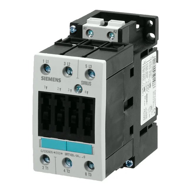
It carries a 24 VDC coil and terminates main circuits via screw-type terminals.
The headline motor ratings tell you what three-phase induction motor this contactor can switch in normal duty. At 500 V AC-3 (starting and running a squirrel-cage motor), it is rated 18.5 kW; at 690 V AC-3, 10 kW. That 18.5 kW at 500 V is the figure that governs most 400/480 V line applications — the contactor handles the inrush and break current for motors up to that power. For AC-2 duty (slip-ring motors, partial-load switching) at 400 V, it is rated 15 kW. For AC-4 (plugging, inching, reversing), the rating drops to 29 A at 400 V — a lower continuous capability because the contactor sees more frequent arc interruption. The switching frequency limits back this up: 1 000 cycles/hour for AC-3, 250 cycles/hour for AC-4. If your application cycles faster than that, the contactor will overheat the arc chamber.
Coil and Control Circuit Details
For DC coil voltages beyond 24 V, the holding currents scale down: 2 A at 60 V, 1 A at 110 V, 0.3 A at 220 V, 6 A at 230 V, 3 A at 400 V. The coil is polarity-sensitive on DC; verify the free-wheel diode or suppression network orientation before wiring.
The mechanical endurance is 10 million cycles, so the armature and spring set outlast most motor starts in a typical line.
Wiring and Conductor Sizing
The screw terminals accept a wide range of conductors. For solid wire: 2x (0.5 to 1.5 mm²), 2x (0.75 to 2.5 mm²), or up to 2x (0.75 to 4 mm²). For stranded wire: 2x (0.75 to 25 mm²). For solid or stranded combined: 2x (0.75 to 16 mm²). At 40 °C ambient, the minimum permissible cross-section is 16 mm² — that is the thermal derating floor for full rated current. The terminal design allows two conductors per clamp, useful for daisy-chaining control power.