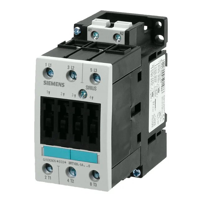
The 55 mm width and 112 mm height fit standard panel layouts; 179 mm depth accounts for the screw-terminal body and arc chamber. Front-side IP20 protects against finger contact; the terminal area is IP00, meaning the wiring compartment is open and must be guarded by the enclosure.
Solid wire accepts 2x (0.5 to 1.5 mm²), 2x (0.75 to 2.5 mm²), or max 2x (0.75 to 4 mm²). Stranded wire takes 2x (0.75 to 25 mm²) — that's the full range for the main power lugs. The minimum permissible cross-section at 40 °C is 16 mm², so you can run a single 16 mm² conductor if the lug is sized for it. Control wiring is separate; verify your coil-suppression diode polarity before energizing.