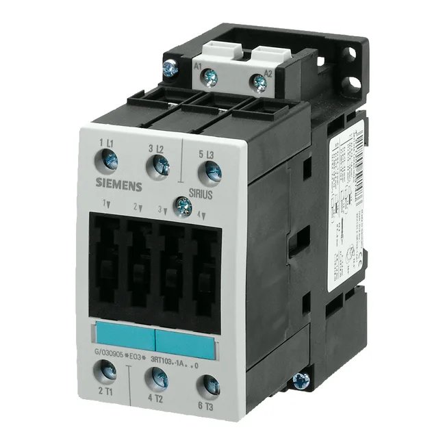
Siemens 3RT1034-1BF40 — Contactors

Siemens 3RT1034-1BF40 SIRIUS Power Contactor, S2 Frame, 55 m

MPN3RT1034-1BF40

Siemens SIRIUS 3RT1034-1BF40, S2 frame power contactor, screw terminals, 55 mm width, 130 mm depth, AC-2 15 kW / AC-4 29 A at 400 V.

Source DocumentedChannel stated on listing & quote
Condition PhotosReal unit photos / video on request
WhatsApp AnswersFast human replies for machine-down parts
Worldwide DispatchDHL/FedEx — transit quoted per order
Independent China distributor & sourcing agent· Listing updated Sep 2026

Specifications

3RT1034-1BF40 — Identification
ParameterValue
Contactor frame sizeS2
3RT1034-1BF40 — Ratings & Performance
ParameterValue
Rated operational current, AC-12, max.10 A
Rated operational current, AC-4 @ 400 V29 A
Rated value @ 400 V3 A
Rated value @ 500 V18.5 kW
Rated value @ 690 V10 kW
Rated value @ 230 V6 A
Rated value @ 24 V10 A
Rated value @ 60 V2 A
Rated value @ 110 V1 A
Rated value @ 220 V0.3 A
3RT1034-1BF40 — Control & Coil
ParameterValue
Control supply voltage typeDC
3RT1034-1BF40 — Contacts & Poles
ParameterValue
Main poles3
Main NO contacts3
Auxiliary contact reliability1 faulty switching per 100 million (17 V, 1 mA)
3RT1034-1BF40 — Protection & Coordination
ParameterValue
Short-circuit coordination type 1, fusefuse gL/gG: 125 A
Short-circuit coordination type 2, fusefuse gL/gG: 63 A
Aux. switch short-circuit protection, fusefuse gL/gG: 10 A
3RT1034-1BF40 — Connection & Mounting
ParameterValue
Main circuit connectionscrew-type terminals
Aux. / control circuit connectionscrew-type terminals
Conductor cross-section, solid2x (0.5 ... 1.5 mm²), 2x (0.75 ... 2.5 mm²), max. 2x (0.75 ... 4 mm²)
Conductor cross-section, solid or stranded2x (0.75 ... 16 mm²)
Conductor cross-section, finely stranded w/ ferrule2x (0.5 ... 1.5 mm²), 2x (0.75 ... 2.5 mm²)
Mounting methodscrew and snap-on mounting onto 35 mm standard mounting rail according to DIN EN 50022
Side-by-side mountingYes
3RT1034-1BF40 — Durability
ParameterValue
Durability (operating cycles, typ.)10 000 000
Durability with aux. switch block (cycles, typ.)10 000 000
3RT1034-1BF40 — Environmental
ParameterValue
Operating temperature range-25 ... +60 °C
Storage temperature range-55 ... +80 °C
Installation altitude, max.2 000 m
3RT1034-1BF40 — Mechanical
ParameterValue
Width55 mm
Height112 mm
Depth130 mm

Product details

Rated for AC-2 duty at 15 kW and AC-4 reversing duty at 29 A, both at 400 V, this contactor handles slip-ring motor starting and reversing applications where frequent jogging or inching is required. The terminals themselves are IP00 — no touch protection at the wiring point, so panel builders should plan for terminal shrouds or additional guarding.

RoHS compliance date is noted as May 1, 2012, and the part carries a substance prohibitance declaration for REACH compliance.

At 55 mm wide and 130 mm deep, the S2 frame occupies one standard DIN-rail module position. Side-by-side mounting is permitted — no derating required for adjacent contactors at rated current. The coil terminals accept 2x 0.5–1.5 mm² solid or 2x 0.75–2.5 mm² stranded. Strip length for screw terminals follows standard practice — 10–12 mm for the larger conductors.

Coil and switching characteristics

The 110 V DC coil draws 10 A at 24 V inrush and 1 A at 110 V holding. Dropout time is 20–30 ms, arcing time 10–15 ms — fast enough for most safety circuits but verify coordination with upstream overcurrent devices. Electrical life depends on duty: 1,200 ops/hour at AC-1, 1,000 at AC-3, 750 at AC-2, and 250 at AC-4 — the reversing duty class limits switching frequency to about 4 operations per minute.

Frequently asked questions

What compliance documentation is available for this contactor?

The part carries a RoHS compliance date of May 1, 2012, and a substance prohibitance declaration for REACH. It is a Siemens SIRIUS product with standard CE and UL certifications typical for the series.

Will the 3RT1034-1BF40 drop into a panel designed for the 3RT1036-1AB00?

Both are SIRIUS S2-frame contactors with the same 55 mm width and DIN-rail mounting pattern, so the mechanical footprint is identical. The key difference is the coil voltage — this unit is 110 V DC, while the 3RT1036-1AB00 uses a different coil. Verify coil supply compatibility before substitution.

What are the main circuit terminal capacities?

Solid conductors: 2x 0.5–1.5 mm², 2x 0.75–2.5 mm², max 2x 0.75–4 mm². Stranded: 2x 0.75–25 mm². Minimum cross-section at 40 °C is 16 mm² for full rated current.

MPN
3RT1034-1BF40