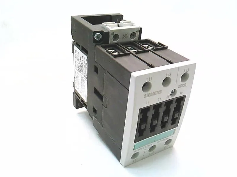
Siemens 3RT1035-1AR60 — Contactors

Siemens 3RT1035-1AR60 SIRIUS Power Contactor, Size S2, 400 V

MPN3RT1035-1AR60

Siemens SIRIUS 3RT1035-1AR60, Size S2 power contactor, 400 V 50 Hz main circuit, screw-type terminals, screw and snap-on mounting onto 35 mm DIN rail.

Source DocumentedChannel stated on listing & quote
Condition PhotosReal unit photos / video on request
WhatsApp AnswersFast human replies for machine-down parts
Worldwide DispatchDHL/FedEx — transit quoted per order
Independent China distributor & sourcing agent· Listing updated Sep 2026

Specifications

3RT1035-1AR60 — Identification
ParameterValue
Contactor frame sizeS2
3RT1035-1AR60 — Ratings & Performance
ParameterValue
Rated operational current, AC-12, max.10 A
Rated operational current, AC-4 @ 400 V35 A
Rated value @ 400 V3 A
Rated value @ 500 V22 kW
Rated value @ 690 V11.4 kW
Rated value @ 230 V6 A
Rated value @ 24 V10 A
Rated value @ 60 V2 A
Rated value @ 110 V1 A
Rated value @ 220 V0.3 A
3RT1035-1AR60 — Control & Coil
ParameterValue
Control supply voltage typeAC
Rated value @ 50 Hz0.8 ... 1.1
Rated value @ 50 Hz400 V
3RT1035-1AR60 — Contacts & Poles
ParameterValue
Main poles3
Main NO contacts3
Auxiliary contact reliability1 faulty switching per 100 million (17 V, 1 mA)
3RT1035-1AR60 — Protection & Coordination
ParameterValue
Short-circuit coordination type 1, fusefuse gL/gG: 125 A
Short-circuit coordination type 2, fusefuse gL/gG: 63 A
Aux. switch short-circuit protection, fusefuse gL/gG: 10 A
3RT1035-1AR60 — Connection & Mounting
ParameterValue
Main circuit connectionscrew-type terminals
Aux. / control circuit connectionscrew-type terminals
Conductor cross-section, solid2x (0.5 ... 1.5 mm²), 2x (0.75 ... 2.5 mm²), max. 2x (0.75 ... 4 mm²)
Conductor cross-section, solid or stranded2x (0.75 ... 16 mm²)
Conductor cross-section, finely stranded w/ ferrule2x (0.5 ... 1.5 mm²), 2x (0.75 ... 2.5 mm²)
Mounting methodscrew and snap-on mounting onto 35 mm standard mounting rail according to DIN EN 50022
Side-by-side mountingYes
3RT1035-1AR60 — Durability
ParameterValue
Durability (operating cycles, typ.)10 000 000
Durability with aux. switch block (cycles, typ.)10 000 000
3RT1035-1AR60 — Environmental
ParameterValue
Operating temperature range-25 ... +60 °C
Storage temperature range-55 ... +80 °C
Installation altitude, max.2 000 m
3RT1035-1AR60 — Mechanical
ParameterValue
Width55 mm
Height112 mm
Depth115 mm
3RT1035-1AR60 — Specifications
ParameterValue
At AC7 ... 20 ms

Product details

Its main circuit is rated at 400 V 50 Hz, delivering 18.5 kW at AC-2 duty and 22 kW at 500 V. At 690 V it handles 11.4 kW, giving you the headroom for a 400 V motor with a healthy voltage drop margin. That covers the typical motor feeder cable range up to 16 mm² without needing adaptor lugs.

Switching frequency and thermal limits for continuous duty

Maximum switching frequency depends on duty class: 1200 operations per hour at AC-1 (resistive), 1000 at AC-3 (motor start/run), and 600 at AC-2 (slip-ring motor). At AC-4 (plugging/inching) the limit drops to 300 ops/h. These are the thermal limits of the contactor — exceeding them will overheat the coil and arc chamber. Mechanical endurance is 10 million operations typical, which for a contactor in a conveyor or pump start/stop cycle at 1000 ops/h translates to roughly 10,000 hours of service before contact wear becomes a consideration.

Auxiliary contact ratings for control circuit integration

The built-in auxiliary contacts are rated at 10 A at 24 V, 6 A at 230 V, and 3 A at 400 V. At 110 V they carry 1 A, and at 220 V only 0.3 A — so if you're feeding a 220 V PLC input from these contacts, check the load current against the 0.3 A limit. Coil operating range spans 0.8 to 1.1 times rated voltage at 50 Hz, and 0.85 to 1.1 at 60 Hz. Operating time is 7 to 20 ms AC, with arcing time between 10 and 15 ms. That's fast enough for most motor start sequences but not for high-speed inching — use a dedicated DC coil contactor for that.

Panel integration and wiring constraints

Dimensions are 112 mm high, 55 mm wide, 115 mm deep — the S2 frame occupies about 6.2 cm² of DIN rail footprint. At 55 mm wide, four units fit in a 220 mm wide enclosure section with room for a 10 mm end bracket. IP20 on the front, IP00 at the terminals — the terminal area is not touch-safe until the enclosure door is closed. In a panel with IP54 rating, this contactor is fine; in an open cabinet, install finger guards over the screw terminals. Wire range on the main circuit: stranded 2x 0.75 to 25 mm², solid or stranded 2x 0.75 to 16 mm². The auxiliary circuit accepts solid 2x 0.5 to 4 mm². Use ferrules on stranded wire for reliable termination in the screw clamp.

Frequently asked questions

What are the key motor ratings for 3RT1035-1AR60?

At 400 V 50 Hz in AC-3 duty, this contactor is rated for 18.5 kW motor load. At 500 V it delivers 22 kW, and at 690 V it handles 11.4 kW. These are the maximum motor power ratings for standard three-phase induction motors.

Will 3RT1035-1AR60 drop into a panel specified around 3RT5034-1AR60 without rewiring?

Both are Size S2 contactors on the same 55 mm wide DIN-rail footprint, so the mechanical fit is identical. However, the 3RT5034-1AR60 is a different series with potentially different coil ratings and auxiliary contact configurations — verify the coil voltage and auxiliary wiring before swapping.

What terminal wire sizes does 3RT1035-1AR60 accept?

Main circuit screw terminals accept stranded wire up to 2x 25 mm², or solid/stranded up to 2x 16 mm². Auxiliary terminals accept solid wire 2x 0.5 to 4 mm², or stranded 2x 0.75 to 2.5 mm².

Where can I buy 3RT1035-1AR60?

This part is sourced and quoted to order against an RFQ through independent distribution channels. Availability and current pricing are confirmed at quote time — submit an RFQ for a firm price and delivery commitment.

MPN
3RT1035-1AR60