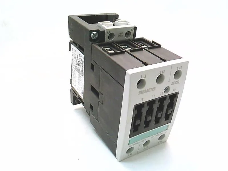
What It Is and Where It Fits
The Siemens 3RT1035-1AU00 is a SIRIUS power contactor in size S2, designed for switching motor loads in industrial control panels. It mounts via screw or snap-on onto a 35 mm standard mounting rail per DIN EN 50022, with a footprint of 55 mm width and 115 mm depth — a compact fit for dense panel layouts where side-by-side mounting is allowed.
Key Ratings and What They Mean for Your Panel
Rated for AC-3 duty at 500 V delivering 22 kW, this contactor handles typical three-phase induction motor loads up to that power. The AC-4 rating at 400 V is 35 A — relevant for reversing or inching applications where the contactor makes and breaks under full load current. At 690 V it still delivers 11.4 kW, so it suits 690 V line supplies common in heavy industrial installations. The rated frequency is 50 Hz, with an operating range of 0.8 to 1.1 times nominal — expect reliable pick-up even on a sagging line. Mechanical life is typical 10,000,000 operations. Maximum switching rates: 1,200 cycles/hour in AC-1, 1,000 cycles/hour in AC-3. The screw-type terminals on the main current circuit accept solid conductors from 2x (0.75... 4 mm²) and stranded up to 2x (0.75... 25 mm²). At 40 °C the minimum permissible cross-section is 16 mm² — that's the derated ampacity floor for continuous current. Pollution degree 3 means it's rated for conductive pollution typical in industrial enclosures without hermetic sealing. Operating temperature range is -25 to +60 °C, storage from -55 to +80 °C. The front of the contactor carries IP20 protection — finger-safe in a closed panel — while the terminals themselves are IP00, so live parts are exposed when the panel door is open. Arcing time is 10 to 15 ms, and the AC operating time is 7 to 20 ms — fast enough for most motor control sequences.
Integration Notes
Side-by-side mounting is permitted, so you can gang multiple contactors on the same DIN rail without derating for heat buildup — just watch the total current draw on the rail's mechanical support. The S2 size means it occupies a standard 55 mm slot; plan your gland plate and wireway clearance around the 115 mm depth for screw-terminal access.
