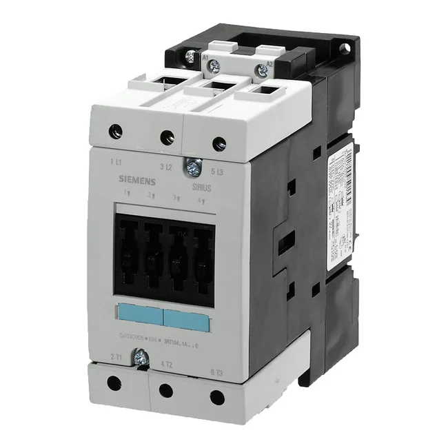
It is a current-production part. The S3 frame (146 mm high, 70 mm wide, 139 mm deep) occupies a standard DIN-rail footprint with room for auxiliary contact blocks on the front.
Rated for AC-3 motor switching at 37 kW at 500 V and 18.6 kW at 690 V — these are the numbers that govern motor starting and running duty. For a 37 kW motor at 500 V, this contactor handles the inrush and breaking current without excessive contact wear. At 690 V the power drops to 18.6 kW because the same current limit applies at higher voltage. The main current circuit uses screw-type terminals, accepting solid conductors 2x (0.5...1.5 mm²), 2x (0.75...2.5 mm²), max. 2x (0.75...4 mm²), and stranded conductors 2x (10...50 mm²). The larger stranded range (up to 50 mm²) handles the motor feeder; the smaller solid range suits control wiring for auxiliary contacts. Auxiliary contact ratings: 10 A at 24 V, 6 A at 230 V, 3 A at 400 V — these are the make/break capacities for the built-in auxiliary contacts. Use them for PLC inputs, contactor feedback, or interlocking. Maximum switching rates: 1,000 1/h at AC-1 and AC-3, 400 1/h at AC-2, 300 1/h at AC-4. IP20 on the front with cover or box terminal; IP00 at the terminal itself. The front IP20 is adequate for finger-safe installation inside a locked panel; the open terminal area requires the panel door to be closed during operation. Operating temperature -25...+60 °C, storage -55...+80 °C. Switching times: arcing time 10...15 ms, total make/break time at AC 10...19 ms. These are fast enough for most motor control sequences; for synchronised switching or soft-starter bypass, the 10 ms spread matters for timing coordination.
The 48 VAC coil variant is less common than the 24 VDC or 230 VAC versions, so lead time may be slightly longer than the popular coil codes. Plan the RFQ with that in mind if the panel was originally specified around this exact voltage.