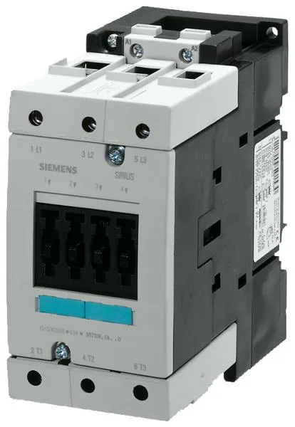
Siemens 3RT1045-1AG20 — Contactors

Siemens SIRIUS 3RT1045-1AG20 Power Contactor, S3 Frame, 45 k

MPN3RT1045-1AG20

Siemens SIRIUS power contactor, 3RT1045-1AG20, S3 frame, screw-type terminals, 45 kW at 500 V AC-3, 21.1 kW at 690 V, IP20 front, current production.

Source DocumentedChannel stated on listing & quote
Condition PhotosReal unit photos / video on request
WhatsApp AnswersFast human replies for machine-down parts
Worldwide DispatchDHL/FedEx — transit quoted per order
Independent China distributor & sourcing agent· Listing updated Sep 2026

Specifications

3RT1045-1AG20 — Identification
ParameterValue
Contactor frame sizeS3
3RT1045-1AG20 — Ratings & Performance
ParameterValue
Rated operational current, AC-12, max.10 A
Rated operational current, AC-4 @ 400 V66 A
Rated value @ 400 V3 A
Rated value @ 500 V45 kW
Rated value @ 690 V21.1 kW
Rated value @ 230 V6 A
Rated value @ 24 V10 A
Rated value @ 60 V2 A
Rated value @ 110 V1 A
Rated value @ 220 V0.3 A
3RT1045-1AG20 — Control & Coil
ParameterValue
Control supply voltage typeAC
Rated value @ 50 Hz0.8 ... 1.1
Rated value @ 50 Hz110 V
3RT1045-1AG20 — Contacts & Poles
ParameterValue
Main poles3
Main NO contacts3
Auxiliary contact reliability1 faulty switching per 100 million (17 V, 1 mA)
3RT1045-1AG20 — Protection & Coordination
ParameterValue
Short-circuit coordination type 1, fusefuse gL/gG: 250 A
Short-circuit coordination type 2, fusefuse gL/gG: 160 A
Aux. switch short-circuit protection, fusefuse gL/gG: 10 A
3RT1045-1AG20 — Connection & Mounting
ParameterValue
Main circuit connectionscrew-type terminals
Aux. / control circuit connectionscrew-type terminals
Conductor cross-section, solid2x (0.5 ... 1.5 mm²), 2x (0.75 ... 2.5 mm²), max. 2x (0.75 ... 4 mm²)
Conductor cross-section, solid or stranded2x (2.5 ... 16 mm²)
Conductor cross-section, finely stranded w/ ferrule2x (0.5 ... 1.5 mm²), 2x (0.75 ... 2.5 mm²)
Mounting methodscrew and snap-on mounting onto 35 mm and 75 mm standard mounting rail
Side-by-side mountingYes
3RT1045-1AG20 — Durability
ParameterValue
Durability (operating cycles, typ.)10 000 000
Durability with aux. switch block (cycles, typ.)10 000 000
3RT1045-1AG20 — Environmental
ParameterValue
Operating temperature range-25 ... +60 °C
Storage temperature range-55 ... +80 °C
Installation altitude, max.2 000 m
3RT1045-1AG20 — Mechanical
ParameterValue
Width70 mm
Height146 mm
Depth139 mm
3RT1045-1AG20 — Specifications
ParameterValue
At AC10 ... 25 ms

Product details

The 3RT1045-1AG20: Rated at 45 kW at 500 V and 21.1 kW at 690 V in AC-3 duty, this contactor handles the full-load current of a three-phase induction motor within those power bands. The screw-type terminals on the main current circuit accept solid conductors from 0.5 mm² up to 4 mm² (two per clamp) and stranded conductors up to 50 mm², which covers the range from control wiring through to the motor feeder cable for a 45 kW load.

Environmental and Protection Ratings

The front of the contactor carries IP20 protection with the cover or box terminal fitted, meaning it is finger-safe from the front once installed in a panel. The terminal area itself is rated IP00, so the contactor must live inside an enclosure that provides the overall panel ingress rating.

Switching Performance and Mechanical Life

Mechanical life is rated at 10 million operations typical, which for a motor-starting application at 1000 operations per hour (AC-3 maximum) translates to over 10,000 hours of continuous cycling before the contactor wears out mechanically. The arcing time sits between 10 and 15 ms, and the total opening time at AC is 10 to 25 ms — fast enough to clear faults in coordination with upstream motor circuit protectors. Maximum operating frequency varies by duty: 900 cycles/hour in AC-1 resistive loads, 1000 cycles/hour in AC-3 motor starting, and 300 cycles/hour in AC-4 plugging or inching duty. If your application involves frequent reversing or jogging, the AC-4 limit is the one that governs contactor life.

The auxiliary contact block (integrated or add-on) carries 10 A at 24 V, 6 A at 230 V, and 3 A at 400 V. These ratings are for the control circuit — feeding the contactor coil, PLC inputs, or status lamps. At 220 V the rating drops to 0.3 A, so if you are switching a 220 V control transformer, verify the inrush does not exceed that figure.

Frequently asked questions

What are the key power ratings for this contactor?

In AC-3 motor duty, it is rated at 45 kW at 500 V and 21.1 kW at 690 V. The AC-1 resistive rating is not directly stated, but the operating frequency for AC-1 is 900 cycles/hour. These are the figures to use when sizing for a three-phase induction motor.

What is the physical size and mounting arrangement?

The S3 frame measures 146 mm high, 70 mm wide, and 139 mm deep. It mounts via screw or snap-on onto 35 mm or 75 mm DIN rail, and side-by-side mounting is permitted without derating.

What terminal types and conductor sizes does it accept?

The main circuit uses screw-type terminals. Solid conductors: 2x 0.5 to 1.5 mm², 2x 0.75 to 2.5 mm², max 2x 0.75 to 4 mm². Stranded conductors: 2x 10 to 50 mm². These cover control wiring through to motor feeder cables for a 45 kW load.

What protection rating does the contactor have?

IP20 on the front with the cover or box terminal fitted. The terminal area itself is IP00, so the contactor must be installed inside an enclosure that provides the overall panel ingress rating.

MPN
3RT1045-1AG20