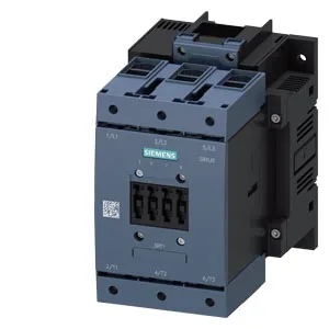
The 3RT1054-1AP30: This is a screw-fixing contactor, not a snap-on DIN rail mount. That means you're bolting it to a backplate or mounting rail, not clipping it onto a DIN rail. Plan for screw terminals on the coil and main circuits.
The 160 A rating at 24 V and 60 V is the continuous current the main contacts can carry in a resistive or lightly inductive circuit. At 400 V, that translates to 29 kW motor load capability — that's your AC-3 duty rating for starting and stopping squirrel-cage motors under load. The coil pulls 220–240 V AC, so it's a standard industrial control voltage. Electrical life depends on duty: AC-3 switching at up to 1,000 operations per hour, AC-4 (inching/plugging) at 130 per hour. That's fast enough for most motor control center applications. Clearance distances are 10 mm upwards/downwards/side, 20 mm forwards — factor that into your enclosure layout for arc flash and heat dissipation.
Wiring and Termination Details
Main circuit power terminals accept stranded wire from 16 to 70 mm² — that's the range for the 160 A rating. Auxiliary contacts (the contactor includes an auxiliary switch block) take solid or stranded wire: 2x 0.5–1.5 mm², 2x 0.75–2.5 mm², or max 2x 0.75–4 mm². Coil terminals are screw-type, same as the main terminals. Dimensions are 172 mm high, 120 mm wide, 170 mm deep. That's a Size S6 footprint — it's a physically large contactor, so verify your enclosure depth and gland plate clearance before committing the BOM line.
The lifecycle stage is current, meaning Siemens still manufactures this exact order code. That's the cleanest sourcing posture you can have for a BOM freeze — no PCN risk, no second-source scramble. Because it's current production, you're not limited to surplus or broker channels. This part is quoted to order through standard distribution. The RFQ route confirms lead time and pricing against your specific quantity.