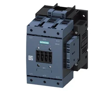
SIRIUS Size S6 Power Contactor — What the Frame Rating Means for Your Panel
The 3RT1054-3AP36 is a SIRIUS power contactor in Size S6, designed for switching motor loads and resistive loads in industrial control panels. The Size S6 frame tells you the contactor's physical footprint and its current-carrying capacity in the SIRIUS family — it is the frame size that determines the main pole rating and the thermal capacity, not the coil voltage. The coil is rated 220-240 V AC at 50/60 Hz with an operating factor of 0.8 at both frequencies, meaning the coil holds in reliably down to 80 % of nominal voltage — important for brownout conditions on a production line. The spring-type terminals on the magnet coil eliminate the need for periodic re-torquing, a maintenance advantage in high-cycle applications. This contactor accepts stranded main circuit wiring from 16 to 70 mm², which covers the range from a 50 A feed to a 200 A motor circuit depending on the duty class. The auxiliary circuit accepts solid or stranded wire 2x 0.25-2.5 mm², typical for control wiring in a 24 VDC or 120 VAC pilot circuit.
Duty-Class Switching Frequencies — AC-3 vs AC-4 Reality
The maximum switching frequency varies sharply by duty class: 1 000 operations per hour in AC-3 (motor starting, normal running) and AC-3e, but only 130 operations per hour in AC-4 (plugging, inching, reversing). If your application requires frequent reversing or jogging, the AC-4 ceiling governs the contactor's thermal capability — exceeding it accelerates contact erosion and may cause welding. In AC-1 (resistive load) the limit is 800 ops/h, and in AC-2 (slip-ring motor starting) it drops to 400 ops/h. The arcing time is 10-15 ms, and the operating times are 40-60 ms for both AC and DC coil supplies — this gives a predictable contact closure window for sequencing logic. The mechanical life is 10 million operations typical, which is the contactor's service life before mechanical wear (spring fatigue, armature wear) — the electrical life will be lower and depends on the switched current and duty class. For a motor circuit running at rated current in AC-3, expect electrical life in the range of 1-2 million operations.
Mounting and Clearance — Panel Layout Constraints
Mounting is by screw fixing with a vertical mounting surface; the contactor can be rotated ±90° and tilted ±22.5° front-to-back. This flexibility helps when fitting into a crowded enclosure, but the clearance distances are fixed: 10 mm upwards, 10 mm downwards, 20 mm forwards, and 10 mm at the side. These are the minimum air gaps to adjacent metalwork or other devices — violating them risks flashover or restricted cooling. The dimensions are 172 mm height, 120 mm width, and 170 mm depth. The depth includes the coil terminals and arc chamber — allow the full 170 mm plus the forward clearance of 20 mm when positioning the contactor near the enclosure door or a busbar system.
Auxiliary Contact Ratings and Temperature Range
The auxiliary switch is rated for 10 A at 24 V, 2 A at 48 V and 60 V, 1 A at 110 V, 0.9 A at 125 V, and 0.3 A at 220 V (-). These are the make/break capacities for the control circuit — a 24 VDC PLC output driving a relay coil draws well under 1 A, so the 10 A rating at 24 V is generous for most signal circuits. The operating temperature range is -25 to +60 °C, suitable for most indoor industrial environments including non-conditioned panel rooms. Storage range is -55 to +80 °C, which covers shipping and warehouse conditions. The full-scale value of 1.1 indicates a 10 % overload capability — the contactor can carry 110 % of its rated current for short periods, useful during motor starting inrush.
Lifecycle and Sourcing — Current Production, Quoted to Order
Sourced through authorized distribution channels. No stock-holding claim is made; the part is quoted to order.