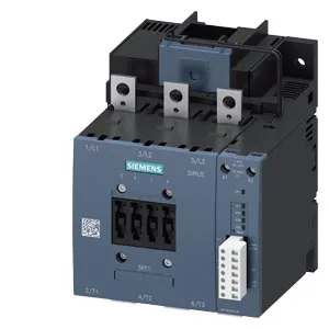
Siemens 3RT1054-6PF35 — Contactors

Siemens 3RT1054-6PF35 SIRIUS Power Contactor, S6

MPN3RT1054-6PF35
Active

Siemens SIRIUS 3RT1054-6PF35 power contactor, size S6, 96-127 VAC 50/60 Hz coil, screw-type terminals, 170 mm depth, 172 mm height, 140 mm width.

StockContact for availability
Lead timeIn Stock wk
MOQ1 pcs
Sourced new & surplus through independent channelsAuthenticity-screened · ESD-safe packingListing updated Jul 2026
How we verify every order →

Specifications

Identification

3RT1054-6PF35 — Identification
ParameterValue
Contactor frame sizeS6

Ratings & Performance

3RT1054-6PF35 — Ratings & Performance
ParameterValue
Rated operational current, AC-12, max.10 A
Rated operational current, AC-4 @ 400 V97 A
Rated value @ 400 V3 A
Rated value @ 500 V2 A
Rated value @ 690 V1 A
Rated value @ 230 V25 hp
Rated value @ 24 V10 A
Rated value @ 60 V2 A
Rated value @ 110 V1 A
Rated value @ 220 V0.3 A

Control & Coil

3RT1054-6PF35 — Control & Coil
ParameterValue
Control supply voltage typeAC/DC
Rated value @ 50 Hz0.6
Rated value @ 50 Hz96 ... 127 V

Contacts & Poles

3RT1054-6PF35 — Contacts & Poles
ParameterValue
Main poles3
Main NO contacts3
Auxiliary contact reliability1 faulty switching per 100 million (17 V, 1 mA)

Protection & Coordination

3RT1054-6PF35 — Protection & Coordination
ParameterValue
Short-circuit coordination type 1, fusegG: 355 A (690 V, 100 kA)
Short-circuit coordination type 2, fusegG: 250 A (690 V, 100 kA), aM: 200 A (690 V, 50 kA), BS88: 250 A (415 V, 50 kA)
Aux. switch short-circuit protection, fusegG: 10 A (500 V, 1 kA)

Connection & Mounting

3RT1054-6PF35 — Connection & Mounting
ParameterValue
Main circuit connectionConnection bar
Aux. / control circuit connectionscrew-type terminals
Conductor cross-section, solid2x (0.5 ... 1.5 mm²), 2x (0.75 ... 2.5 mm²), max. 2x (0.75 ... 4 mm²)
Conductor cross-section, solid or stranded2x (0,5 ... 1,5 mm²), 2x (0,75 ... 2,5 mm²), max. 2x (0,75 ... 4 mm²)
Conductor cross-section, finely stranded w/ ferrule2x (0.5 ... 1.5 mm²), 2x (0.75 ... 2.5 mm²)
Mounting methodscrew fixing
Side-by-side mountingYes

Durability

3RT1054-6PF35 — Durability
ParameterValue
Durability (operating cycles, typ.)10 000 000
Durability with aux. switch block (cycles, typ.)10 000 000

Environmental

3RT1054-6PF35 — Environmental
ParameterValue
Operating temperature range-25 ... +60 °C
Storage temperature range-55 ... +80 °C
Installation altitude, max.2 000 m

Mechanical

3RT1054-6PF35 — Mechanical
ParameterValue
Width140 mm
Height172 mm
Depth170 mm

Specifications

3RT1054-6PF35 — Specifications
ParameterValue
At AC80 ... 90 ms

Product details

S6 Frame, 96-127 VAC Coil — What the Ratings Mean for Fit

The 3RT1054-6PF35 is a Siemens SIRIUS power contactor in frame size S6, meaning it occupies the physical envelope and terminal footprint of that size class — 172 mm tall, 140 mm wide, 170 mm deep. The coil is rated 96-127 VAC at 50/60 Hz, with a pickup threshold of 0.8 × rated value and a dropout of 0.6 × rated value, so it will hold in on a nominal 110 VAC control circuit but may drop out if the line sags below about 77 VAC. The main power terminals accept stranded cable from 25 mm² up to 120 mm² — that is the range for the load-side wiring. The coil and auxiliary terminals are screw-type, accepting solid or stranded wire: 2× (0.5-1.5 mm²), 2× (0.75-2.5 mm²), or max 2× (0.75-4 mm²). This is a contactor you land with a screwdriver, not a spring-cage tool.

Switching Duty and Mechanical Life

The contactor is rated for different switching frequencies depending on the utilization category: 1 000 operations per hour at AC-3 (motor starting), 800 at AC-1 (resistive), 400 at AC-2 (slip-ring motors), and 130 at AC-4 (plugging/inching). The AC-3e rating also sits at 1 000 ops/h. The mechanical life is 10 million operations typical — that is the contactor body itself, not the contacts under load. Arcing time is 10-15 ms, and the operate time (both AC and DC coil) is 80-90 ms. That gives you a total break time around 90-105 ms from coil de-energization to arc extinction — relevant for coordinating with upstream protection.

Mounting and Clearance Requirements

Mounting is by screw fixing (four 9 mm holes) on a vertical surface. The contactor can be rotated ±90° or tilted ±22.5° front-to-back. Minimum clearances to adjacent parts: 10 mm upwards, 10 mm downwards, 10 mm at the side, and 20 mm forwards. That 20 mm forward clearance is the arc-chute side — respect it to avoid flashover between phases. Operating temperature range is -25 to +60 °C; storage range is -55 to +80 °C. The full-scale value of 1.1 means the contactor can be operated at 110% of rated voltage continuously — but check the coil thermal limit if the ambient is at the high end.

Auxiliary Contacts and Coil Options

The contactor is equipped with an auxiliary switch block. The auxiliary contact ratings are: 10 A at 24 V, 2 A at 48 V, 2 A at 60 V, and 1 A at 110 V — all at the rated value. These are the dry switching limits; derate for inductive loads. The coil termination is screw-type, and the coil itself is rated for continuous duty at 96-127 VAC. The initial pickup value is 0.8 × rated, so at 96 V nominal the pickup threshold is about 77 V.

Frequently asked questions

What size cable does the main power terminal accept?

The main power terminals accept stranded cable from 25 mm² up to 120 mm². The coil and auxiliary terminals accept solid or stranded wire: 2× (0.5-1.5 mm²), 2× (0.75-2.5 mm²), or max 2× (0.75-4 mm²), all screw-type.

MPN
3RT1054-6PF35