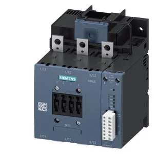
SIRIUS Size S6 — panel fit and conductor range
The 3RT1054-6PP35: This is a Siemens SIRIUS power contactor in the Size S6 frame, measuring 172 mm high by 140 mm wide by 170 mm deep, with screw fixing to the mounting surface. The main power circuit accepts stranded conductors from 25 mm² up to 120 mm², while the auxiliary/coil terminals take solid or stranded wire in ranges from 0.5 mm² to 4 mm² depending on the number of conductors per clamp. Mounting position is flexible: the contactor can be rotated ±90° on a vertical surface or tilted ±22.5° forward and back, which simplifies integration into existing panel layouts where space is tight.
Coil circuit and auxiliary contact ratings
The magnet coil uses screw-type terminals and is rated for a control voltage of 200–277 V AC, with an operating tolerance of 0.8 to 1.1 times the rated value — meaning the coil pulls in reliably even if the control supply sags to 160 V. Built-in auxiliary contacts are rated for switching: 10 A at 24 V, 2 A at 48 V or 60 V, and 1 A at 110 V — these cover typical PLC-level signal loads without an external interface relay. Mechanical endurance is rated at 10 million operating cycles typical, which aligns with the SIRIUS family's service life for conveyor and pump cycling applications.
Switching frequency by duty class
Maximum switching rates vary by load type: 1,000 operations per hour in AC-3 (motor starting) and AC-3e duty, 800 ops/h in AC-1 (resistive), 400 ops/h in AC-2 (slip-ring motors), and 130 ops/h in AC-4 (plugging/inching). The contactor's operating time (coil pickup and dropout) is 80–90 ms for both AC and DC control, with an arcing time of 10–15 ms — this timing matters when coordinating with upstream short-circuit protection devices.
Thermal and clearance constraints
Operating ambient temperature range is -25 °C to +60 °C, with storage from -55 °C to +80 °C — the -25 °C floor means it can be installed in unheated enclosures in temperate climates without a space heater. Minimum clearances to adjacent components: 10 mm upwards, 10 mm downwards, 10 mm to the side, and 20 mm forwards — these are the free-air spacing requirements for heat dissipation and arc containment.