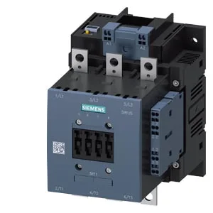
Its rated control supply voltage of 21... 27.3 V DC means the coil holds in at 21 V and drops out below that — critical to verify your DC supply rail doesn't sag under load. The 10 A rated current at 24 V DC on the auxiliary contacts tells you the auxiliary circuit can handle a modest pilot-duty load, but the 1 A rating at 110 V DC is the real limit for DC inductive switching. Screw fixing and a vertical mounting surface with +/-90° rotation and +/-22.5° tilt gives panel builders flexibility in tight enclosures, but the 170 mm depth and 120 mm width demand a 200 mm deep cabinet minimum for cable bending radius.
Switching rates and duty cycles
The maximum operating rates tell you what this contactor can sustain thermally: 800 operations per hour in AC-1 resistive duty, 750 in AC-3 motor starting, but only 130 in AC-4 plugging/reversing. For a conveyor drive cycling every 30 seconds, AC-3 at 750 ops/h is comfortable; a press brake that reverses every 5 seconds exceeds the AC-4 limit and requires a larger frame or a dedicated reversing contactor pair. Arcing time of 10... 15 ms and operating times of 80... 90 ms (both AC and DC) are standard for this frame size. The 0.6 power factor at 50/60 Hz indicates the contactor is rated for motor loads with typical lagging PF — no derating needed for standard induction motors.
Main power terminals accept 25... 120 mm² stranded copper — that's a 2/0 AWG equivalent, sized for a 100+ A motor circuit. The coil terminals are spring-type, accepting 2x (0.25... 2.5 mm²) solid or stranded, so you can daisy-chain the control wiring without ring terminals. Four 9 mm mounting holes on a screw-fixing pattern; spacing requires 10 mm clearance upwards, downwards, and to the side, plus 20 mm forwards for arc-chamber ventilation.