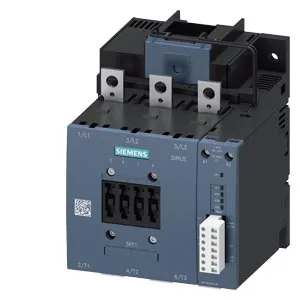
Siemens 3RT1055-6PF35 — Contactors

Siemens 3RT1055-6PF35 SIRIUS Power Contactor, S6

MPN3RT1055-6PF35
Active

Siemens SIRIUS 3RT1055-6PF35 power contactor, size S6, 96-127 VAC 50/60 Hz coil, screw-type terminals, 172 x 170 x 140 mm (HxWxD), screw fixing.

StockContact for availability
Lead timeIn Stock wk
MOQ1 pcs
Sourced new & surplus through independent channelsAuthenticity-screened · ESD-safe packingListing updated Jul 2026
How we verify every order →

Specifications

Identification

3RT1055-6PF35 — Identification
ParameterValue
Contactor frame sizeS6

Ratings & Performance

3RT1055-6PF35 — Ratings & Performance
ParameterValue
Rated operational current, AC-12, max.10 A
Rated operational current, AC-4 @ 400 V132 A
Rated value @ 400 V3 A
Rated value @ 500 V2 A
Rated value @ 690 V1 A
Rated value @ 230 V30 hp
Rated value @ 24 V10 A
Rated value @ 60 V2 A
Rated value @ 110 V1 A
Rated value @ 220 V0.3 A

Control & Coil

3RT1055-6PF35 — Control & Coil
ParameterValue
Control supply voltage typeAC/DC
Rated value @ 50 Hz0.6
Rated value @ 50 Hz96 ... 127 V

Contacts & Poles

3RT1055-6PF35 — Contacts & Poles
ParameterValue
Main poles3
Main NO contacts3
Auxiliary contact reliability1 faulty switching per 100 million (17 V, 1 mA)

Protection & Coordination

3RT1055-6PF35 — Protection & Coordination
ParameterValue
Short-circuit coordination type 1, fusegG: 355 A (690 V, 100 kA)
Short-circuit coordination type 2, fusegG: 315 A (690 V, 100 kA), aM: 200 A (690 V, 50 kA), BS88: 315 A (415 V, 50 kA)
Aux. switch short-circuit protection, fusegG: 10 A (500 V, 1 kA)

Connection & Mounting

3RT1055-6PF35 — Connection & Mounting
ParameterValue
Main circuit connectionConnection bar
Aux. / control circuit connectionscrew-type terminals
Conductor cross-section, solid2x (0.5 ... 1.5 mm²), 2x (0.75 ... 2.5 mm²), max. 2x (0.75 ... 4 mm²)
Conductor cross-section, solid or stranded2x (0,5 ... 1,5 mm²), 2x (0,75 ... 2,5 mm²), max. 2x (0,75 ... 4 mm²)
Conductor cross-section, finely stranded w/ ferrule2x (0.5 ... 1.5 mm²), 2x (0.75 ... 2.5 mm²)
Mounting methodscrew fixing
Side-by-side mountingYes

Durability

3RT1055-6PF35 — Durability
ParameterValue
Durability (operating cycles, typ.)10 000 000
Durability with aux. switch block (cycles, typ.)10 000 000

Environmental

3RT1055-6PF35 — Environmental
ParameterValue
Operating temperature range-25 ... +60 °C
Storage temperature range-55 ... +80 °C
Installation altitude, max.2 000 m

Mechanical

3RT1055-6PF35 — Mechanical
ParameterValue
Width140 mm
Height172 mm
Depth170 mm

Specifications

3RT1055-6PF35 — Specifications
ParameterValue
At AC80 ... 90 ms

Product details

SIRIUS S6 Power Contactor — 172 x 170 x 140 mm Envelope

The Siemens 3RT1055-6PF35 is a SIRIUS-branded power contactor in the S6 frame size, designed for heavy motor switching and resistive load applications in industrial control panels. It measures 172 mm high by 140 mm wide by 170 mm deep and mounts via screw fixing to a vertical surface, with ±90° rotatability and ±22.5° tilt front-to-back for panel layout flexibility. The coil is rated 96-127 VAC at 50/60 Hz with a 0.8 pick-up and 1.1 drop-out factor, using screw-type terminals for the magnet coil connection. Operating time is 80-90 ms for both AC and DC actuation, with an arcing time of 10-15 ms.

Duty-Cycle Ratings and Switching Frequency Ceilings

The contactor's maximum switching frequency varies by duty class: 800 operations per hour in AC-1 (resistive), 750/h in AC-3 and AC-3e (squirrel-cage motor starting), 300/h in AC-2 (slip-ring motor), and 130/h in AC-4 (plugging/inching). For a motor-starting application at AC-3, the 750/h ceiling means a minimum cycle time of about 4.8 seconds — relevant when sizing for high-speed indexing or frequent start-stop sequences. Mechanical endurance is rated at 10,000,000 operating cycles typical, which under AC-3 duty at 750 ops/h translates to over 13,000 hours of continuous cycling before mechanical wear becomes a factor. The auxiliary switch is included as standard, with contact ratings of 10 A at 24 V, 2 A at 48 V and 60 V, and 1 A at 110 V — sufficient for PLC input or relay coil pilot duty.

Termination, Clearances, and Environmental Limits

Main power circuit accepts stranded conductors from 25 to 120 mm² via a single 9 mm diameter hole per pole. Auxiliary circuits use screw terminals accepting solid or stranded wire: 2x 0.5-1.5 mm², 2x 0.75-2.5 mm², or max 2x 0.75-4 mm² per clamp. Minimum clearance distances to adjacent components: 10 mm upwards, 10 mm downwards, 10 mm at the side, and 20 mm forwards. Operating temperature range is -25 to +60 °C, storage from -55 to +80 °C. The power factor at rated load is 0.6 at both 50 and 60 Hz.

Sourcing and Lifecycle — Active Production

For BOM planning, the part is sourced to order against an RFQ. No stock-holding claim is made; each order is validated against the manufacturer's current lead time.

MPN
3RT1055-6PF35