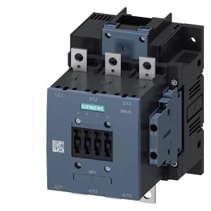
It carries a 110-127 V AC coil via screw-type terminals and accepts stranded main conductors from 25 to 120 mm². Rated operating cycles hit 750 per hour in AC-3 duty — that's the motor-switching curve, not the resistive AC-1 curve at 800 ops/h. The arcing time sits at 10-15 ms, so sequence coordination with upstream protection needs that window accounted for.
Clearances and mounting
Screw fixing through a 9 mm hole, one mounting point. That forward clearance is the one that catches panel builders — the arc chute depth pushes out. Mounting surface vertical, rotatable ±90°, tiltable ±22.5° front-to-back. Dimensions: 172 mm high, 120 mm wide, 170 mm deep.
Termination and wire range
Main power circuit accepts stranded 25-120 mm². The control circuit (auxiliary switch present) takes solid or stranded wire: 2x 0.5-1.5 mm², 2x 0.75-2.5 mm², max 2x 0.75-4 mm². Coil terminals are screw-type. If you are landing 120 mm² on the mains, plan the bend radius into the gland plate — the 170 mm depth includes the termination zone.
Duty cycles and thermal limits
Mechanical life typical at 10 million operations. The switching frequency limits vary by load type: AC-1 (resistive) max 800 ops/h, AC-3 (motor start/run) max 750 ops/h, AC-4 (plugging/inching) max 130 ops/h. If the application needs frequent reversing, the AC-4 ceiling is the binding constraint — not the AC-3 number.
No discontinuation notice or last-time-buy date is recorded. If your BOM calls for the 3RT1056-6AF36-ZX95, the supply channel is open — no forced migration to a successor part.